
Chapter Eleven Real Arithmetic
11.1 Chapter Overview
This chapter discusses the implementation of floating point arithmetic computation in assembly language. By the conclusion of this chapter you should be able to translate arithmetic expressions and assignment statements involving floating point operands from high level languages like Pascal and C/C++ into 80x86 assembly language.
11.2 Floating Point Arithmetic
When the 8086 CPU first appeared in the late 1970's, semiconductor technology was not to the point where Intel could put floating point instructions directly on the 8086 CPU. Therefore, they devised a scheme whereby they could use a second chip to perform the floating point calculations - the floating point unit (or FPU)1. They released their original floating point chip, the 8087, in 1980. This particular FPU worked with the 8086, 8088, 80186, and 80188 CPUs. When Intel introduced the 80286 CPU, they released a redesigned 80287 FPU chip to accompany it. Although the 80287 was compatible with the 80386 CPU, Intel designed a better FPU, the 80387, for use in 80386 systems. The 80486 CPU was the first Intel CPU to include an on-chip floating point unit. Shortly after the release of the 80486, Intel introduced the 80486sx CPU that was an 80486 without the built-in FPU. To get floating point capabilities on this chip, you had to add an 80487 chip, although the 80487 was really nothing more than a full-blown 80486 which took over for the "sx" chip in the system. Intel's Pentium chips provide a high-performance floating point unit directly on the CPU. There is no (Intel) floating point coprocessor available for the Pentium chip.
Collectively, we will refer to all these chips as the 80x87 FPU. Given the obsolescence of the 8086, 80286, 8087, 80287, 80387, and 80487 chips, this text will concentrate on the Pentium and later chips. There are some differences between the Pentium floating point units and the earlier FPUs. If you need to write code that will execute on those earlier machines, you should consult the appropriate Intel documentation for those devices.
11.2.1 FPU Registers
The 80x86 FPUs add 13 registers to the 80x86 and later processors: eight floating point data registers, a control register, a status register, a tag register, an instruction pointer, and a data pointer. The data registers are similar to the 80x86's general purpose register set insofar as all floating point calculations take place in these registers. The control register contains bits that let you decide how the FPU handles certain degenerate cases like rounding of inaccurate computations, it contains bits that control precision, and so on. The status register is similar to the 80x86's flags register; it contains the condition code bits and several other floating point flags that describe the state of the FPU. The tag register contains several groups of bits that determine the state of the value in each of the eight general purpose registers. The instruction and data pointer registers contain certain state information about the last floating point instruction executed. We will not consider the last three registers in this text, see the Intel documentation for more details.
11.2.1.1 FPU Data Registers
The FPUs provide eight 80 bit data registers organized as a stack. This is a significant departure from the organization of the general purpose registers on the 80x86 CPU that comprise a standard general-purpose register set. HLA refers to these registers as ST0, ST1, ..., ST7.
The biggest difference between the FPU register set and the 80x86 register set is the stack organization. On the 80x86 CPU, the AX register is always the AX register, no matter what happens. On the FPU, however, the register set is an eight element stack of 80 bit floating point values (see Figure 11.1).

Figure 11.1 FPU Floating Point Register Stack
ST0 refers to the item on the top of the stack, ST1 refers to the next item on the stack, and so on. Many floating point instructions push and pop items on the stack; therefore, ST1 will refer to the previous contents of ST0 after you push something onto the stack. It will take some thought and practice to get used to the fact that the registers are changing under you, but this is an easy problem to overcome.
11.2.1.2 The FPU Control Register
When Intel designed the 80x87 (and, essentially, the IEEE floating point standard), there were no standards in floating point hardware. Different (mainframe and mini) computer manufacturers all had different and incompatible floating point formats. Unfortunately, much application software had been written taking into account the idiosyncrasies of these different floating point formats. Intel wanted to design an FPU that could work with the majority of the software out there (keep in mind, the IBM PC was three to four years away when Intel began designing the 8087, they couldn't rely on that "mountain" of software available for the PC to make their chip popular). Unfortunately, many of the features found in these older floating point formats were mutually incompatible. For example, in some floating point systems rounding would occur when there was insufficient precision; in others, truncation would occur. Some applications would work with one floating point system but not with the other. Intel wanted as many applications as possible to work with as few changes as possible on their 80x87 FPUs, so they added a special register, the FPU control register, that lets the user choose one of several possible operating modes for their FPU.
The 80x87 control register contains 16 bits organized as shown in Figure 11.2.
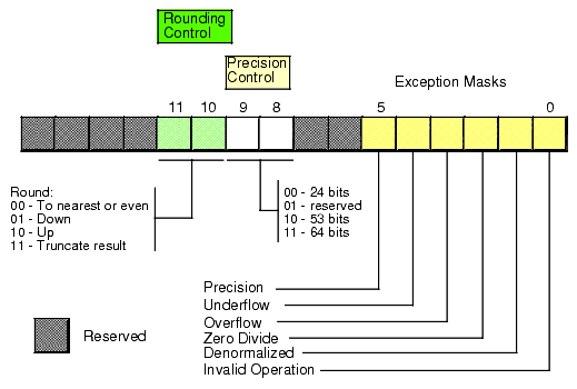
Figure 11.2 FPU Control Register
Bits 10 and 11 provide rounding control according to the following values:
The "00" setting is the default. The FPU rounds values above one-half of the least significant bit up. It rounds values below one-half of the least significant bit down. If the value below the least significant bit is exactly one-half of the least significant bit, the FPU rounds the value towards the value whose least significant bit is zero. For long strings of computations, this provides a reasonable, automatic, way to maintain maximum precision.
The round up and round down options are present for those computations where it is important to keep track of the accuracy during a computation. By setting the rounding control to round down and performing the operation, then repeating the operation with the rounding control set to round up, you can determine the minimum and maximum ranges between which the true result will fall.
The truncate option forces all computations to truncate any excess bits during the computation. You will rarely use this option if accuracy is important to you. However, if you are porting older software to the FPU, you might use this option to help when porting the software. One place where this option is extremely useful is when converting a floating point value to an integer. Since most software expects floating point to integer conversions to truncate the result, you will need to use the truncation rounding mode to achieve this.
Bits eight and nine of the control register specify the precision during computation. This capability is provided to allow compatibility with older software as required by the IEEE 754 standard. The precision control bits use the following values:
Some CPUs may operate faster with floating point values whose precision is 53 bits (i.e., 64-bit floating point format) rather than 64 bits (i.e., 80-bit floating point format). Please see the documentation for your specific processor for details. Generally, the CPU defaults these bits to %11 to select the 64-bit mantissa precision.
Bits zero through five are the exception masks. These are similar to the interrupt enable bit in the 80x86's flags register. If these bits contain a one, the corresponding condition is ignored by the FPU. However, if any bit contains zero, and the corresponding condition occurs, then the FPU immediately generates an interrupt so the program can handle the degenerate condition.
Bit zero corresponds to an invalid operation error. This generally occurs as the result of a programming error. Problems which raise the invalid operation exception include pushing more than eight items onto the stack or attempting to pop an item off an empty stack, taking the square root of a negative number, or loading a non-empty register.
Bit one masks the denormalized interrupt that occurs whenever you try to manipulate denormalized values. Denormalized exceptions occur when you load arbitrary extended precision values into the FPU or work with very small numbers just beyond the range of the FPU's capabilities. Normally, you would probably not enable this exception. If you enable this exception and the FPU generates this interrupt, the HLA run-time system raises the ex.fDenormal exception.
Bit two masks the zero divide exception. If this bit contains zero, the FPU will generate an interrupt if you attempt to divide a nonzero value by zero. If you do not enable the zero division exception, the FPU will produce NaN (not a number) whenever you perform a zero division. It's probably a good idea to enable this exception by programming a zero into this bit. Note that if your program generates this interrupt, the HLA run-time system will raise the ex.fDivByZero exception.
Bit three masks the overflow exception. The FPU will raise the overflow exception if a calculation overflows or if you attempt to store a value which is too large to fit into a destination operand (e.g., storing a large extended precision value into a single precision variable). If you enable this exception and the FPU generates this interrupt, the HLA run-time system raises the ex.fOverflow exception.
Bit four, if set, masks the underflow exception. Underflow occurs when the result is too small to fit in the destination operand. Like overflow, this exception can occur whenever you store a small extended precision value into a smaller variable (single or double precision) or when the result of a computation is too small for extended precision. If you enable this exception and the FPU generates this interrupt, the HLA run-time system raises the ex.fUnderflow exception.
Bit five controls whether the precision exception can occur. A precision exception occurs whenever the FPU produces an imprecise result, generally the result of an internal rounding operation. Although many operations will produce an exact result, many more will not. For example, dividing one by ten will produce an inexact result. Therefore, this bit is usually one since inexact results are very common. If you enable this exception and the FPU generates this interrupt, the HLA run-time system raises the ex.InexactResult exception.
Bits six and thirteen through fifteen in the control register are currently undefined and reserved for future use. Bit seven is the interrupt enable mask, but it is only active on the 8087 FPU; a zero in this bit enables 8087 interrupts and a one disables FPU interrupts.
The FPU provides two instructions, FLDCW (load control word) and FSTCW (store control word), that let you load and store the contents of the control register. The single operand to these instructions must be a 16 bit memory location. The FLDCW instruction loads the control register from the specified memory location, FSTCW stores the control register into the specified memory location. The syntax for these instructions is
fldcw( mem16 );

fstcw( mem16 );
Here's some example code that sets the rounding control to "truncate result" and sets the rounding precision to 24 bits:
static

	fcw16: word;

		.

		.

		.

		fstcw( fcw16 );

		mov( fcw16, ax );

		and( $f0ff, ax );      // Clears bits 8-11.

		or( $0c00, ax );       // Rounding control=%11, Precision = %00.

		mov( ax, fcw16 );

		fldcw( fcw16 );
11.2.1.3 The FPU Status Register
The FPU status register provides the status of the coprocessor at the instant you read it. The FSTSW instruction stores the16 bit floating point status register into a word variable. The status register is a 16 bit register, its layout appears in Figure 11.3.
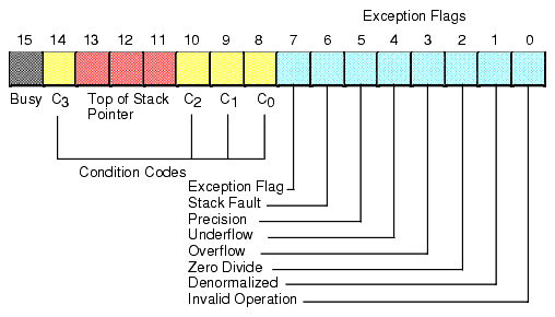
Figure 11.3 The FPU Status Register
Bits zero through five are the exception flags. These bits are appear in the same order as the exception masks in the control register. If the corresponding condition exists, then the bit is set. These bits are independent of the exception masks in the control register. The FPU sets and clears these bits regardless of the corresponding mask setting.
Bit six indicates a stack fault. A stack fault occurs whenever there is a stack overflow or underflow. When this bit is set, the C1 condition code bit determines whether there was a stack overflow (C1=1) or stack underflow (C1=0) condition.
Bit seven of the status register is set if any error condition bit is set. It is the logical OR of bits zero through five. A program can test this bit to quickly determine if an error condition exists.
Bits eight, nine, ten, and fourteen are the coprocessor condition code bits. Various instructions set the condition code bits as shown in the following table:
Bits 11-13 of the FPU status register provide the register number of the top of stack. During computations, the FPU adds (modulo eight) the logical register numbers supplied by the programmer to these three bits to determine the physical register number at run time.
Bit 15 of the status register is the busy bit. It is set whenever the FPU is busy. Most programs will have little reason to access this bit.
11.2.2 FPU Data Types
The FPU supports seven different data types: three integer types, a packed decimal type, and three floating point types. The integer type provides for 64-bit integers, although it is often faster to do the 64-bit arithmetic using the integer unit of the CPU (see the chapter on Advanced Arithmetic). Certainly it is often faster to do 16-bit and 32-bit integer arithmetic using the standard integer registers. The packed decimal type provides a 17 digit signed decimal (BCD) integer. The primary purpose of the BCD format is to convert between strings and floating point values. The remaining three data types are the 32 bit, 64 bit, and 80 bit floating point data types we've looked at so far. The 80x87 data types appear in Figure 11.4, Figure 11.5, and Figure 11.6.
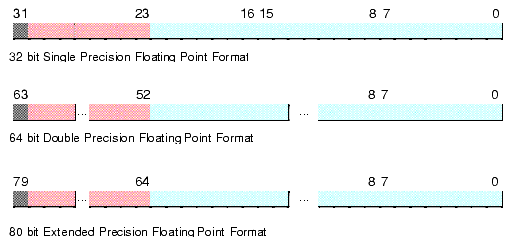
Figure 11.4 FPU Floating Point Formats
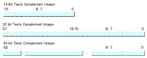
Figure 11.5 FPU Integer Formats

Figure 11.6 FPU Packed Decimal Format
The FPU generally stores values in a normalized format. When a floating point number is normalized, the H.O. bit of the mantissa is always one. In the 32 and 64 bit floating point formats, the FPU does not actually store this bit, the FPU always assumes that it is one. Therefore, 32 and 64 bit floating point numbers are always normalized. In the extended precision 80 bit floating point format, the FPU does not assume that the H.O. bit of the mantissa is one, the H.O. bit of the mantissa appears as part of the string of bits.
Normalized values provide the greatest precision for a given number of bits. However, there are a large number of non-normalized values which we cannot represent with the 80-bit format. These values are very close to zero and represent the set of values whose mantissa H.O. bit is not zero. The FPUs support a special 80-bit form known as denormalized values. Denormalized values allow the FPU to encode very small values it cannot encode using normalized values, but at a price. Denormalized values offer fewer bits of precision than normalized values. Therefore, using denormalized values in a computation may introduce some slight inaccuracy into a computation. Of course, this is always better than underflowing the denormalized value to zero (which could make the computation even less accurate), but you must keep in mind that if you work with very small values you may lose some accuracy in your computations. Note that the FPU status register contains a bit you can use to detect when the FPU uses a denormalized value in a computation.
1Intel has also referred to this device as the Numeric Data Processor (NDP), Numeric Processor Extension (NPX), and math coprocessor.
|