
Note: All photographs appearing on this page are freely usable for any purpose. Links to high-resolution versions of the pictures appear below each picture.
Soldering Header Pins on a Teensy 3.2
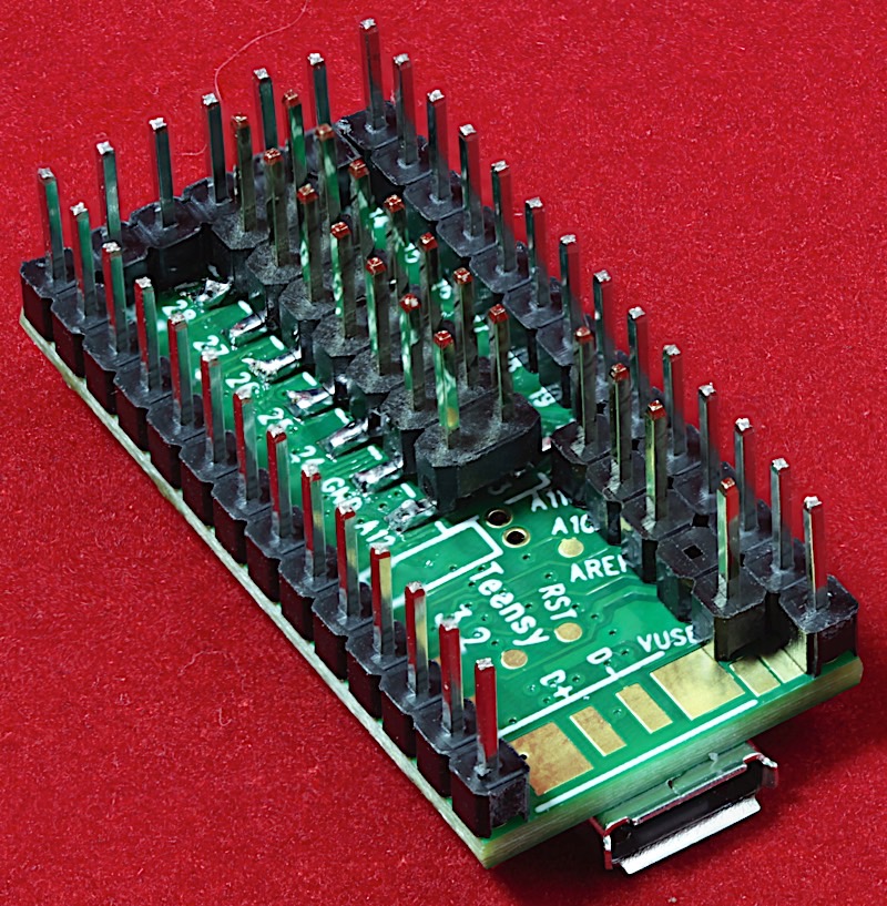
High-resolution image
Overview
The Teensy 3.2 interfaces to off-board devices through a set of through-hole pin and SMT (surface mount technology) pad connections. Because of the small size of the Teensy board and the layout of the SMT pads, it can be rather difficult to solder headers (especially the SMT headers) onto the Teensy 3.2. This guide describes how to accomplish this without damaging the Teensy 3.2.
Note: this guide assumes you will be connecting pins to more than a couple Teensy 3.2 units. It describes how to build a jig to simplify the construction of a fully-connected Teensy. If you're only going to assemble one or two Teensy 3.2 units, the assembly instructions for the Ethernet Watchdog Board describe another way to solder pins onto a Teensy 3.2 without having to first build a jig.
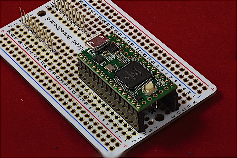
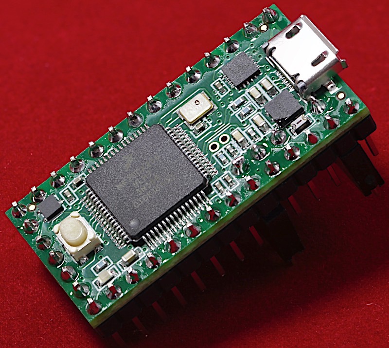
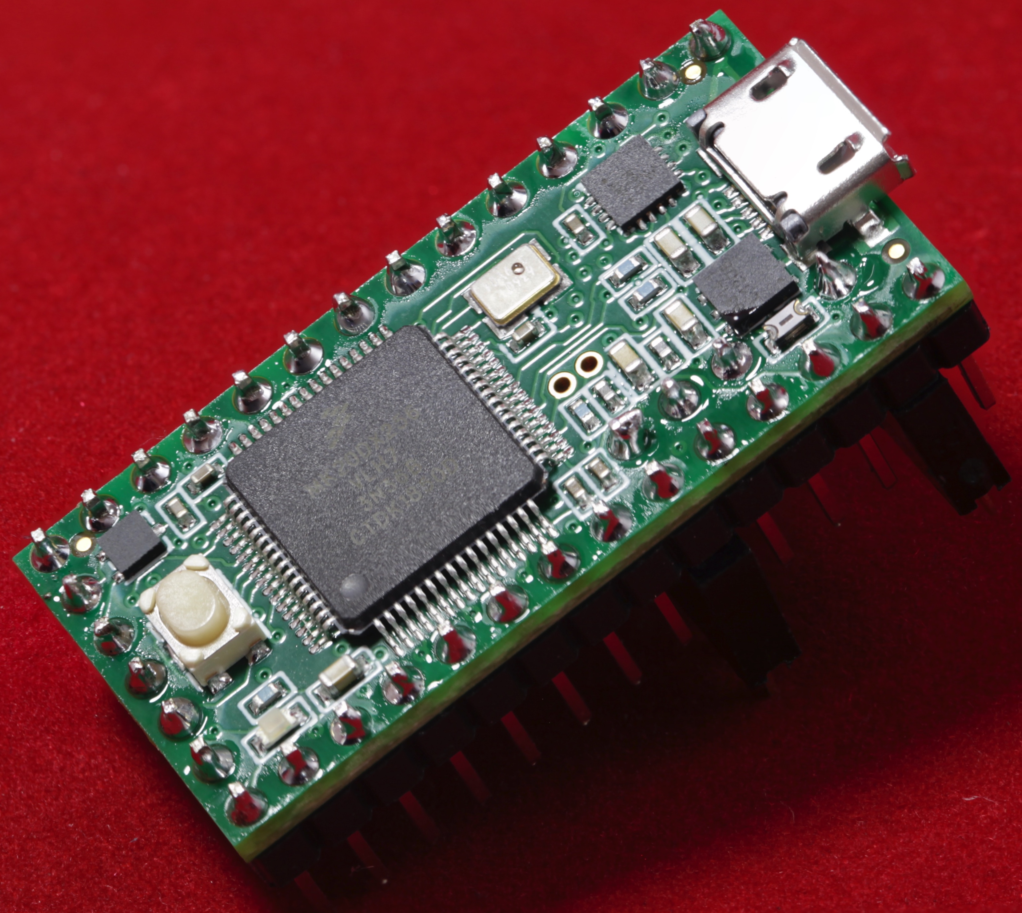
Before doing anything else, plug the Teensy 3.2 into a USB port and verify that it functions. If the Teensy 3.2 is brand-new (likely, if you're reading this guide), then it comes with the blink program preinstalled. If you've already programmed the Teensy, fire up the Arduino IDE and load the blink example onto the Teensy and verify that it can blink the LED.
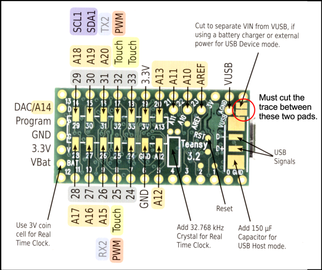
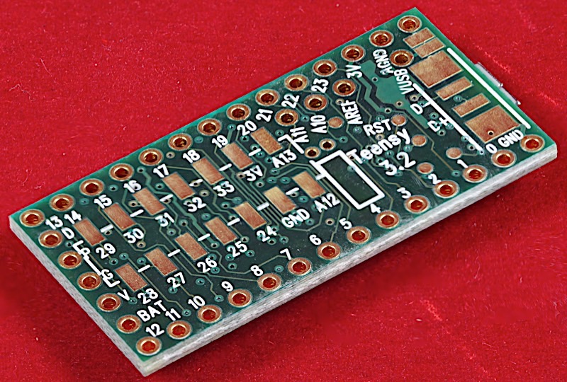
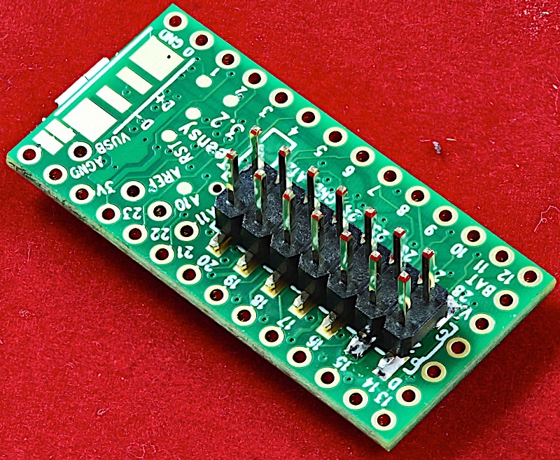
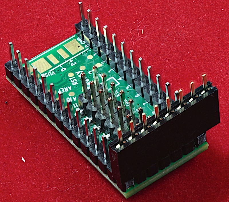
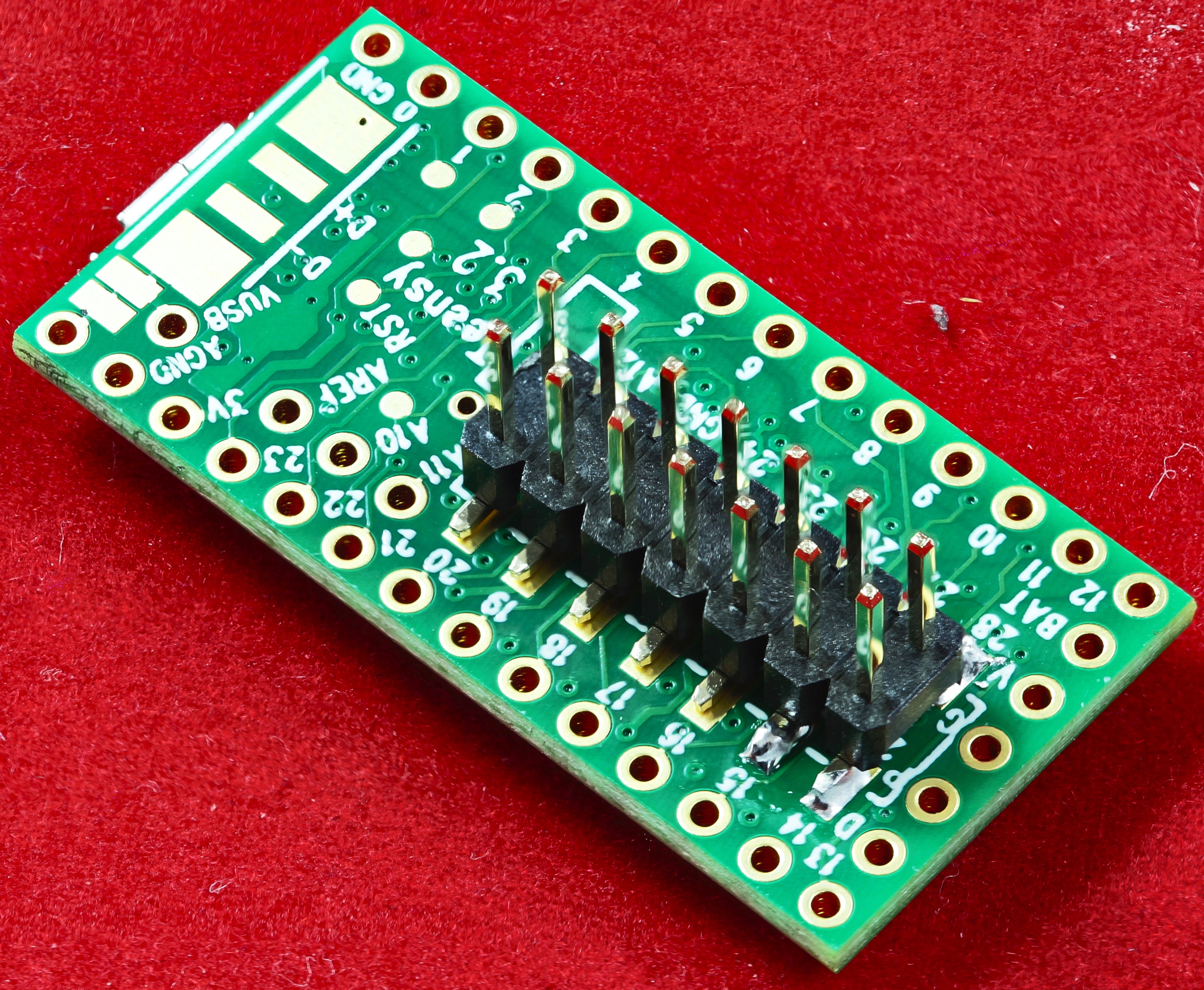
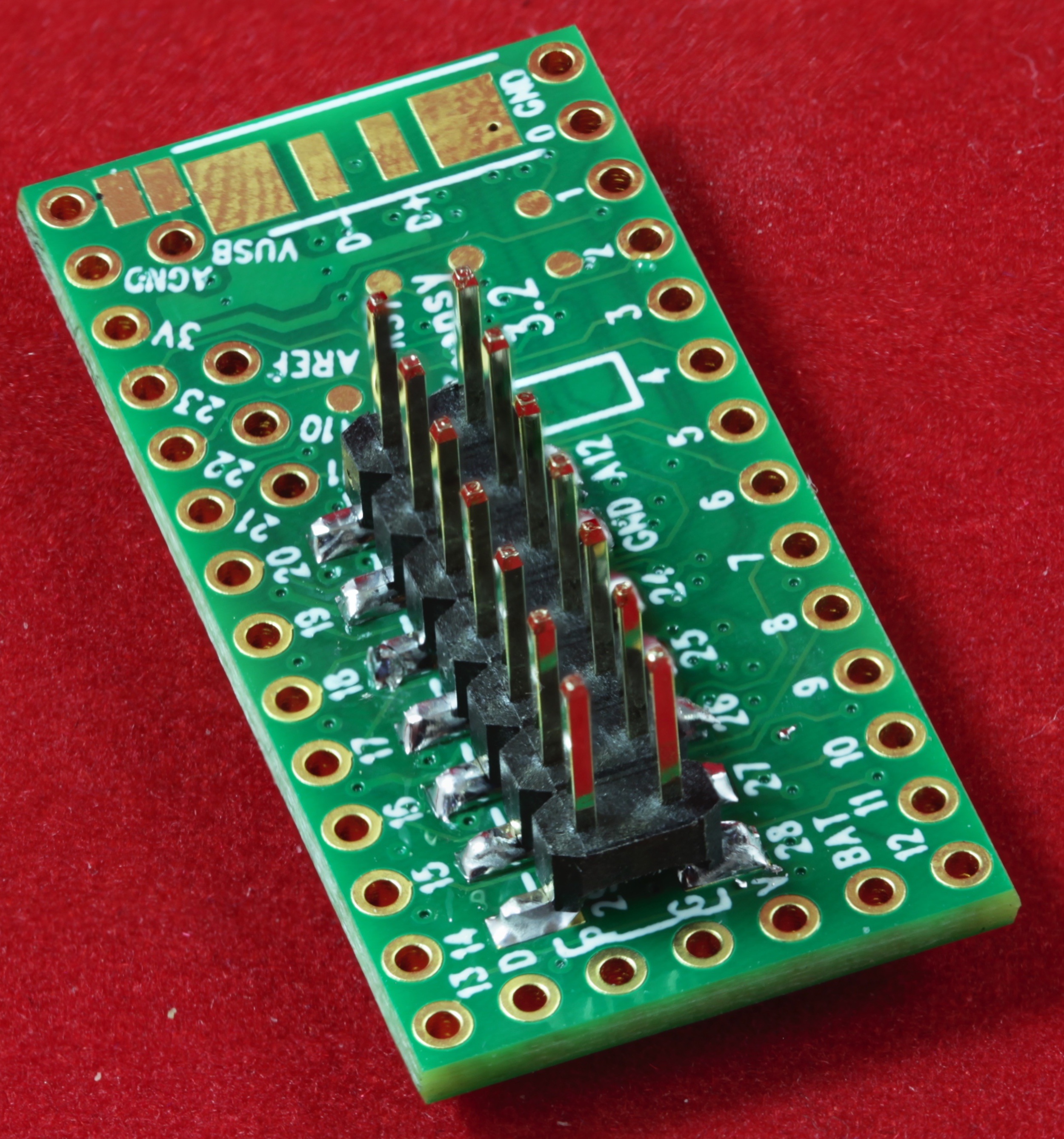
Once you've verified that the Teensy 3.2 is functional, be sure to cut the VIN/VUSB trace on the bottom size of the Teensy 3.2 if you don't plan on powering the Teensy 3.2 from the USB port. Typically, when putting headers on Teensy 3.2 SBCs, you're probably intending to power the Teensy from external circuitry, not the USB connector. For proper operation (and to prevent a short), this tiny trace must be cut (See the back side of the “Welcome to Teensy 3.2” card that ships with the Teensy 3.2). Of course if you are intending to power the Teensy 3.2 from the USB port, leave this trace intact.
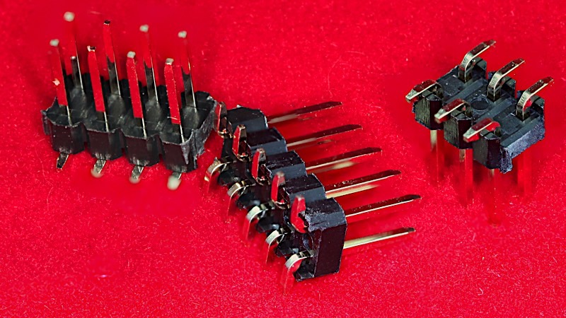
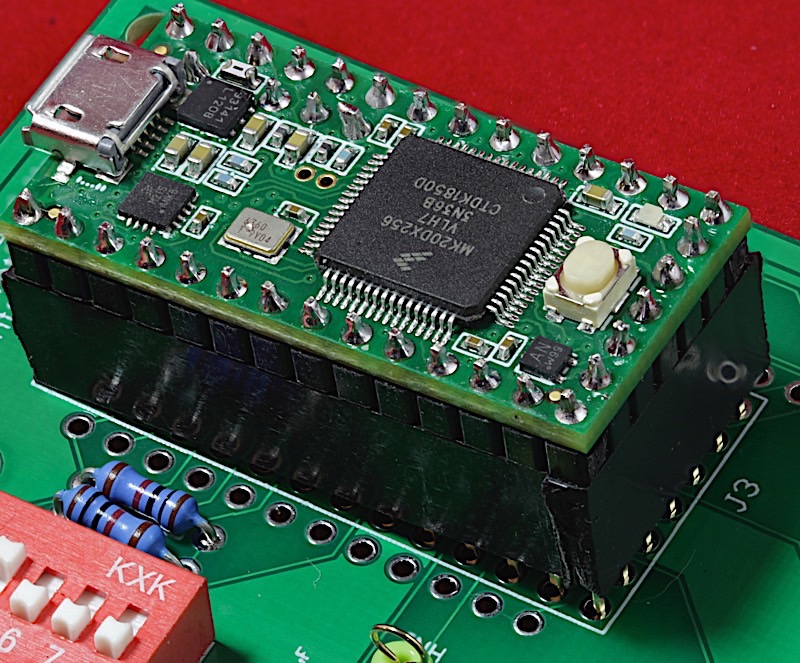
Perhaps the hardest part of building an EWB is finding the 2.54mm pitch two-row SMT/SMD male headers. The EWB requires a 2x7 SMT male header to provide access to the extra I/O pins present only on pads on the bottom of the Teensy 3.2:
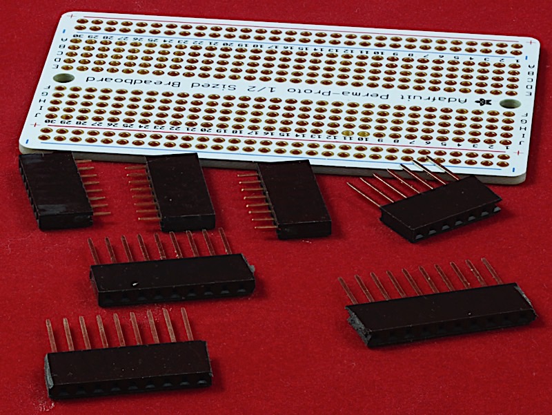
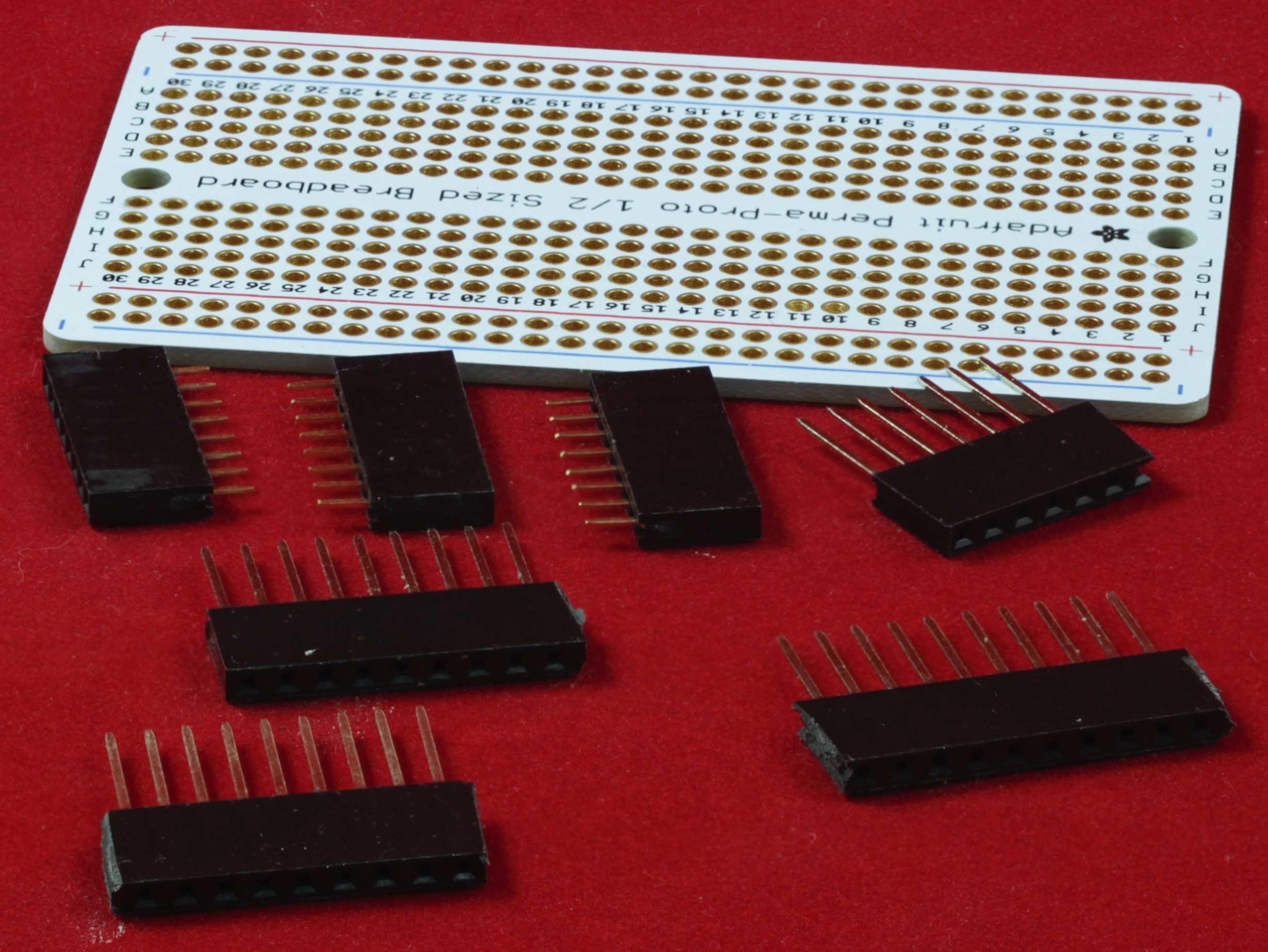
This set of instructions describes how to solder pins onto a Teensy 3.2 using a specially-made jig. To build a jig, you will need the following parts:
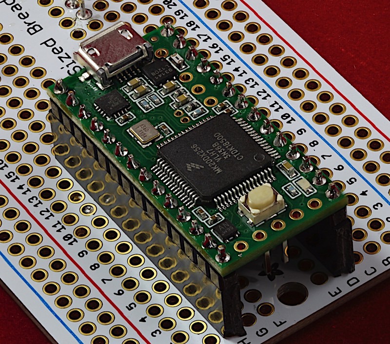
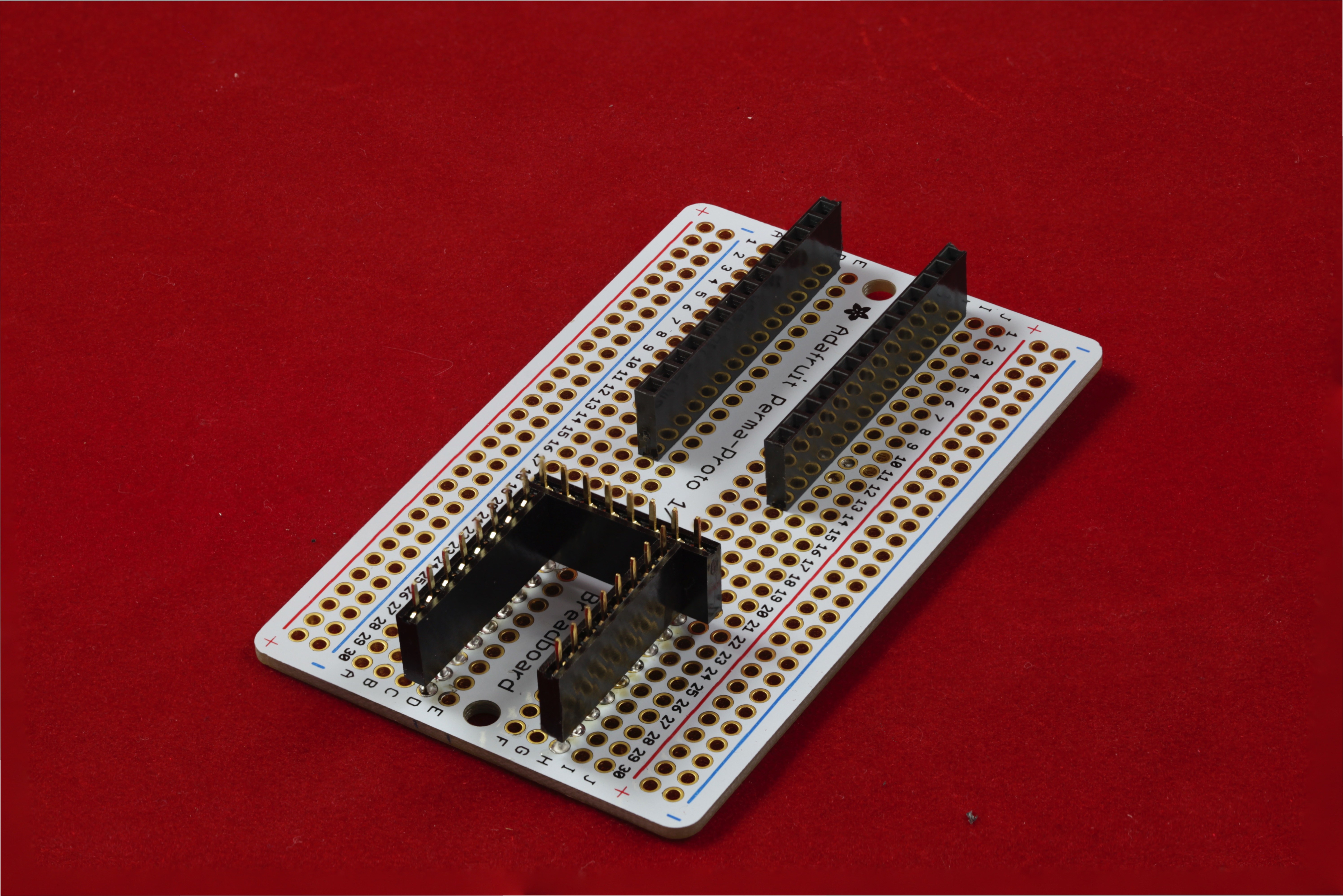
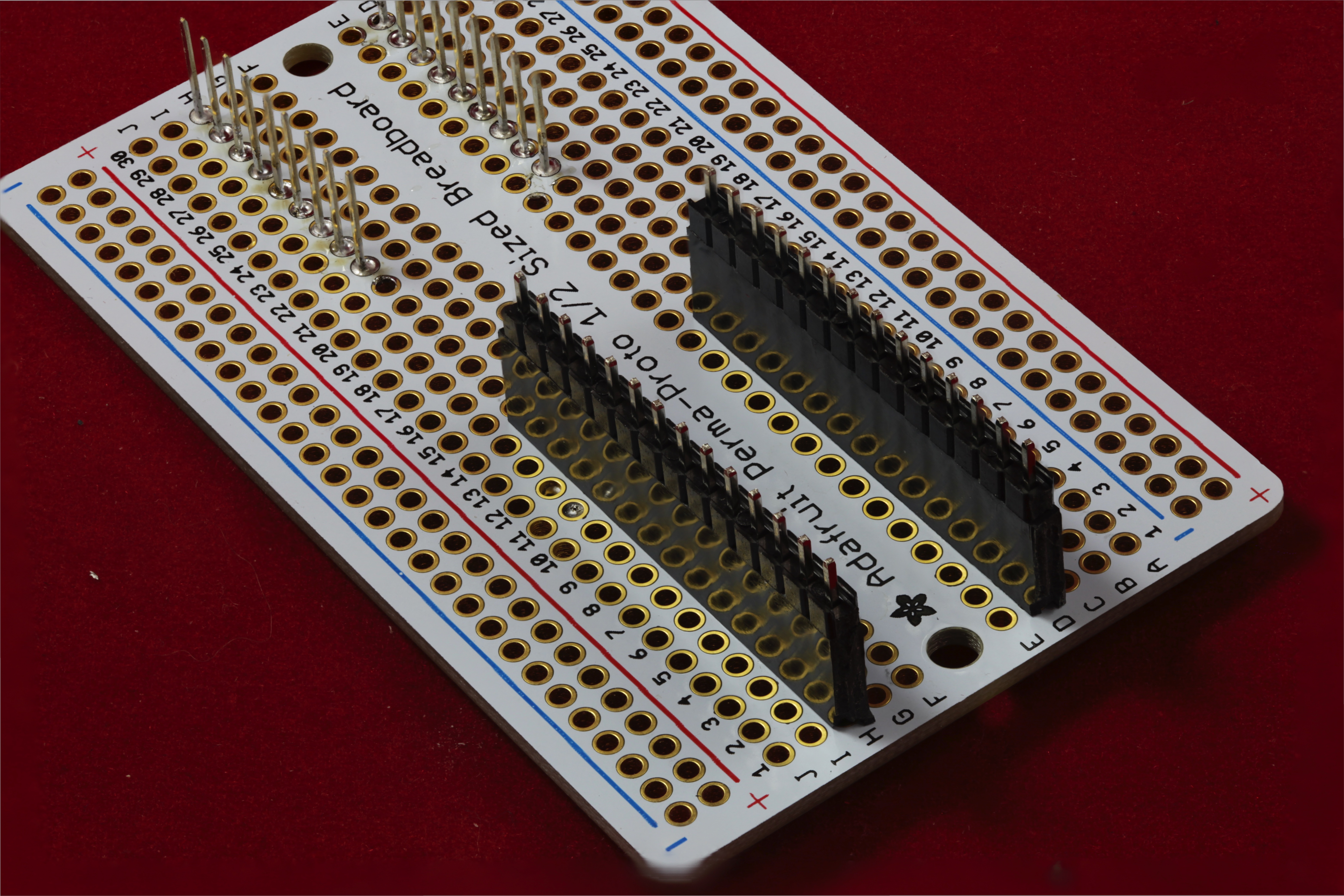
- A small prototyping board (a PCB with lots of holes on tenth-inch centers that you can solder pins onto). The Adafruit Perma-proto 1/2 Sized Breadboard is perfect for this task. In addition, you will need (3) 8-pin female headers with solder tails, (2) nine-pin headers with long pins (e.g., wire-wrap pins), and (2) 14-pin female sockets with solder pins.
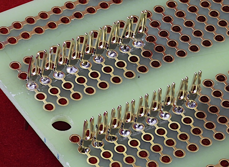
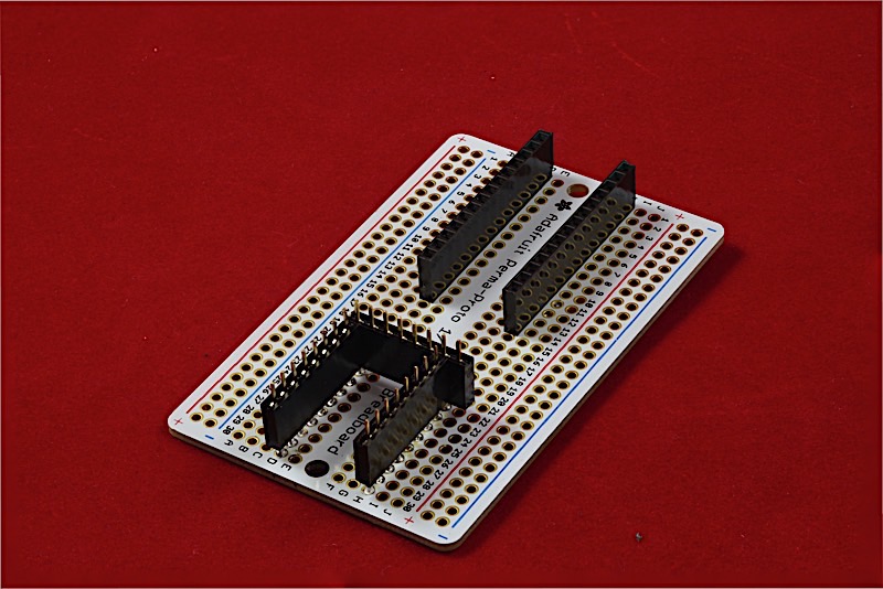
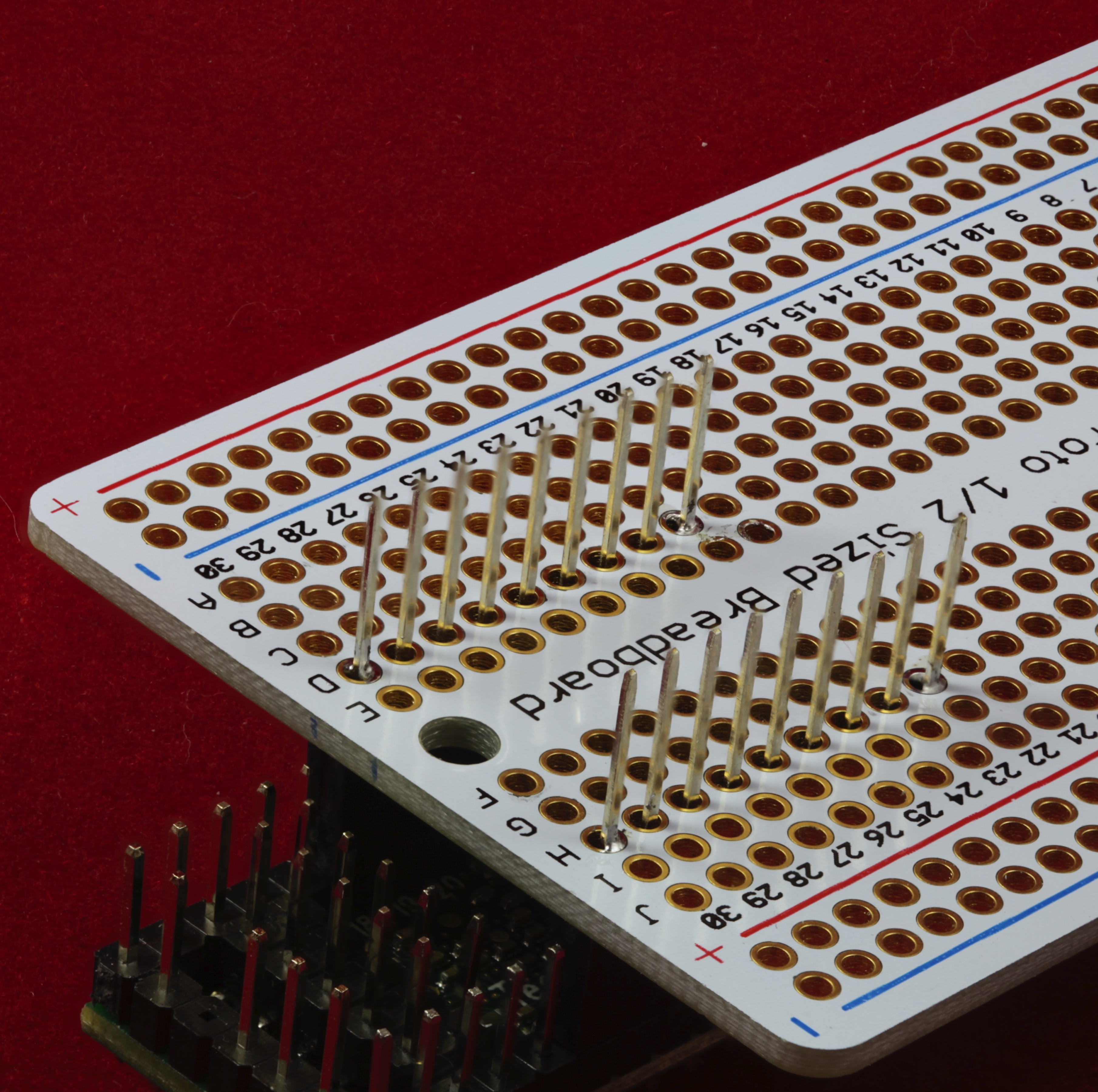
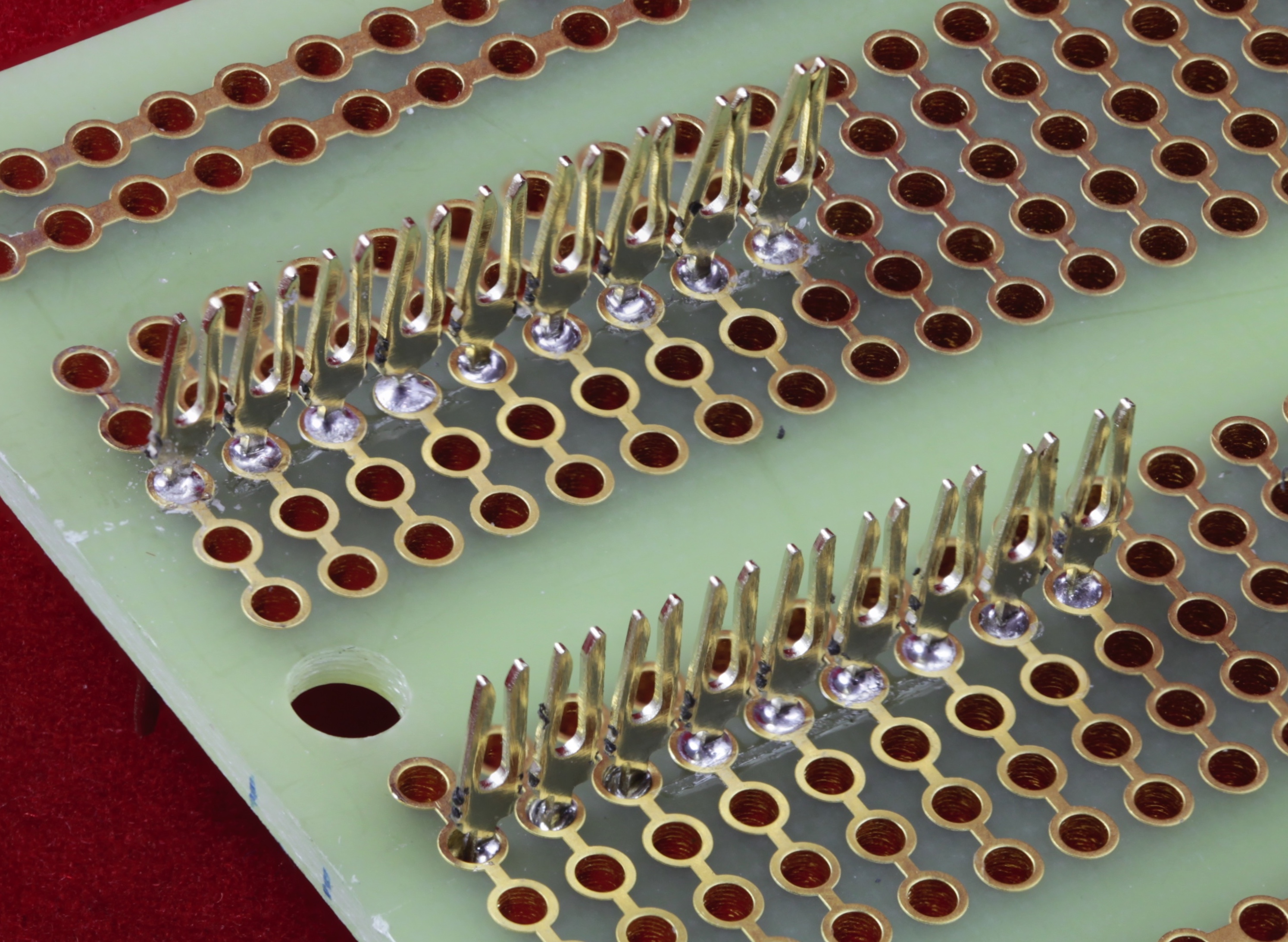
Solder the two 9-pin female headers on one each of the proto board, 0.7" apart. I actually use a (previously wired) Teensy 3.2 with header pins to hold the headers in place while I soldered the pins onto the proto board. Note that the jig is going to use the pins, not the sockets, so ensure that the pins are pointing up on the "business side" (top) of the board.
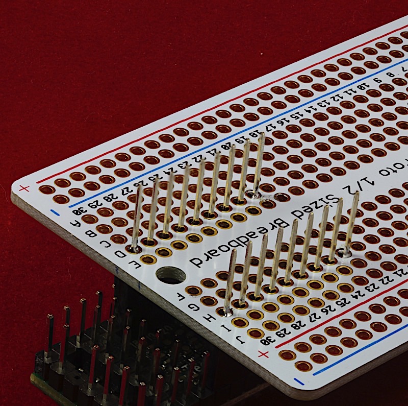
Note that no electrical signals will ever flow through the pins, so the soldering job isn't critical at this point. Solder for strength rather than electrical quality.
Flip the board over. The jig will actually use the pins, not the sockets. So the next step is to pull the sockets off the pins.
I used a pair of wire snippers to gently lift the plastic sockets off the pins:
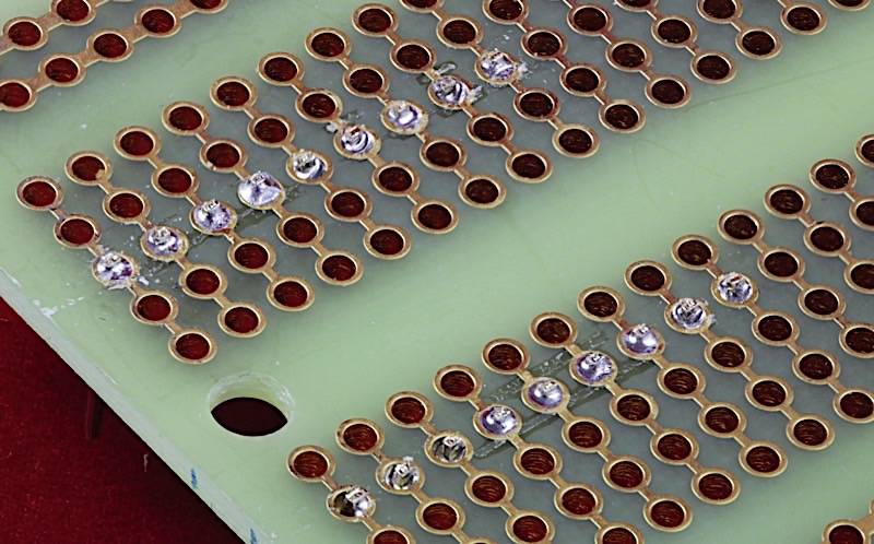
Because we're not using the pin/sockets, use the wire snippers to trim all the connectors off the bottom of the board:
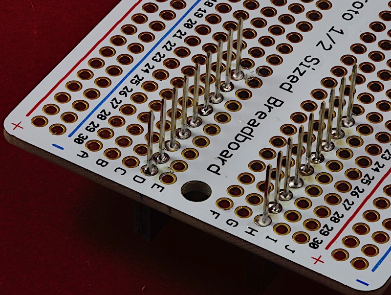
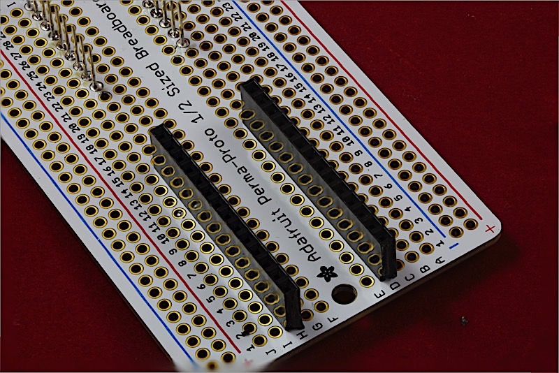
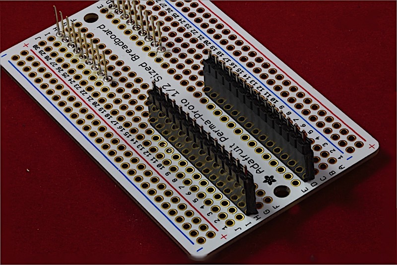
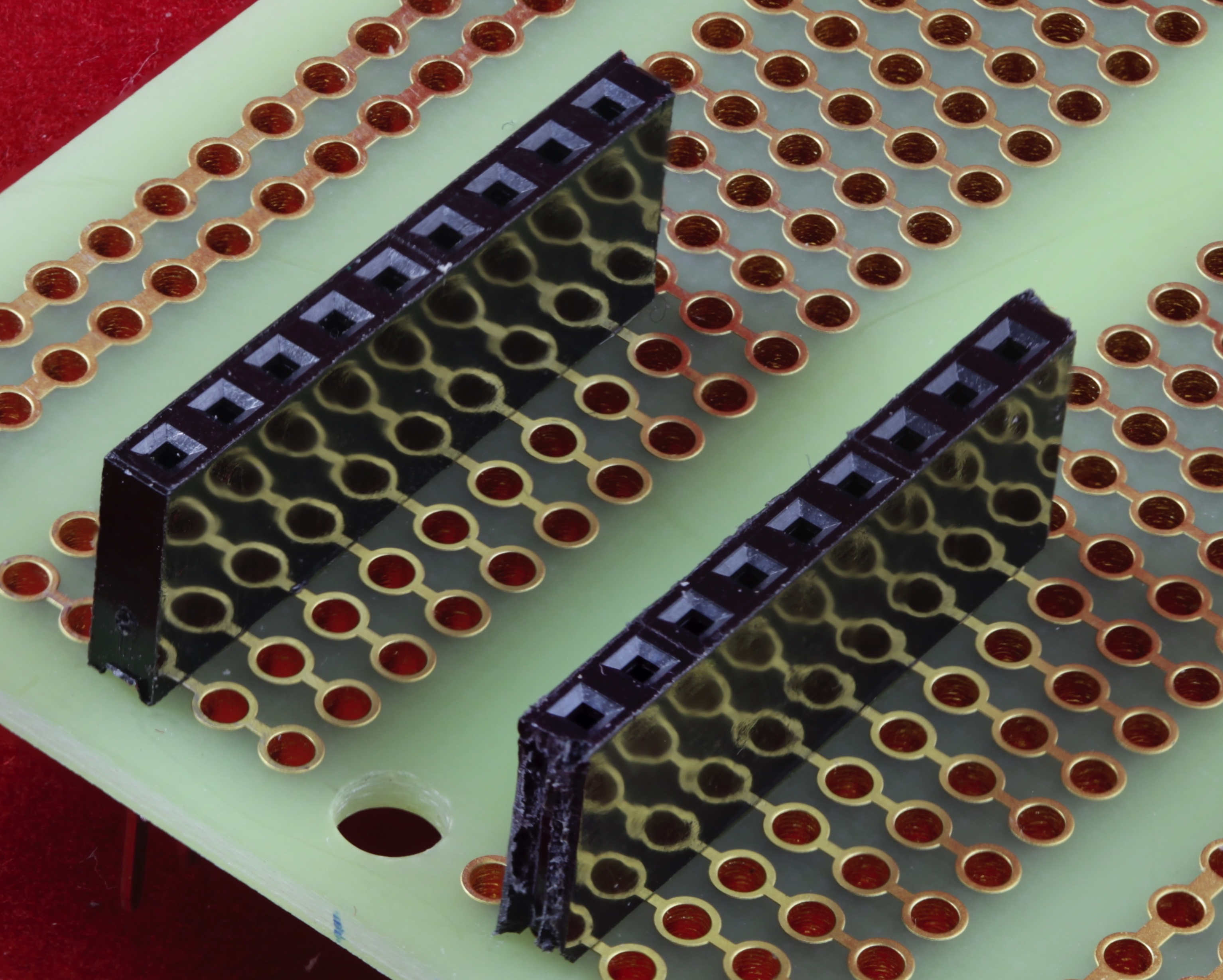
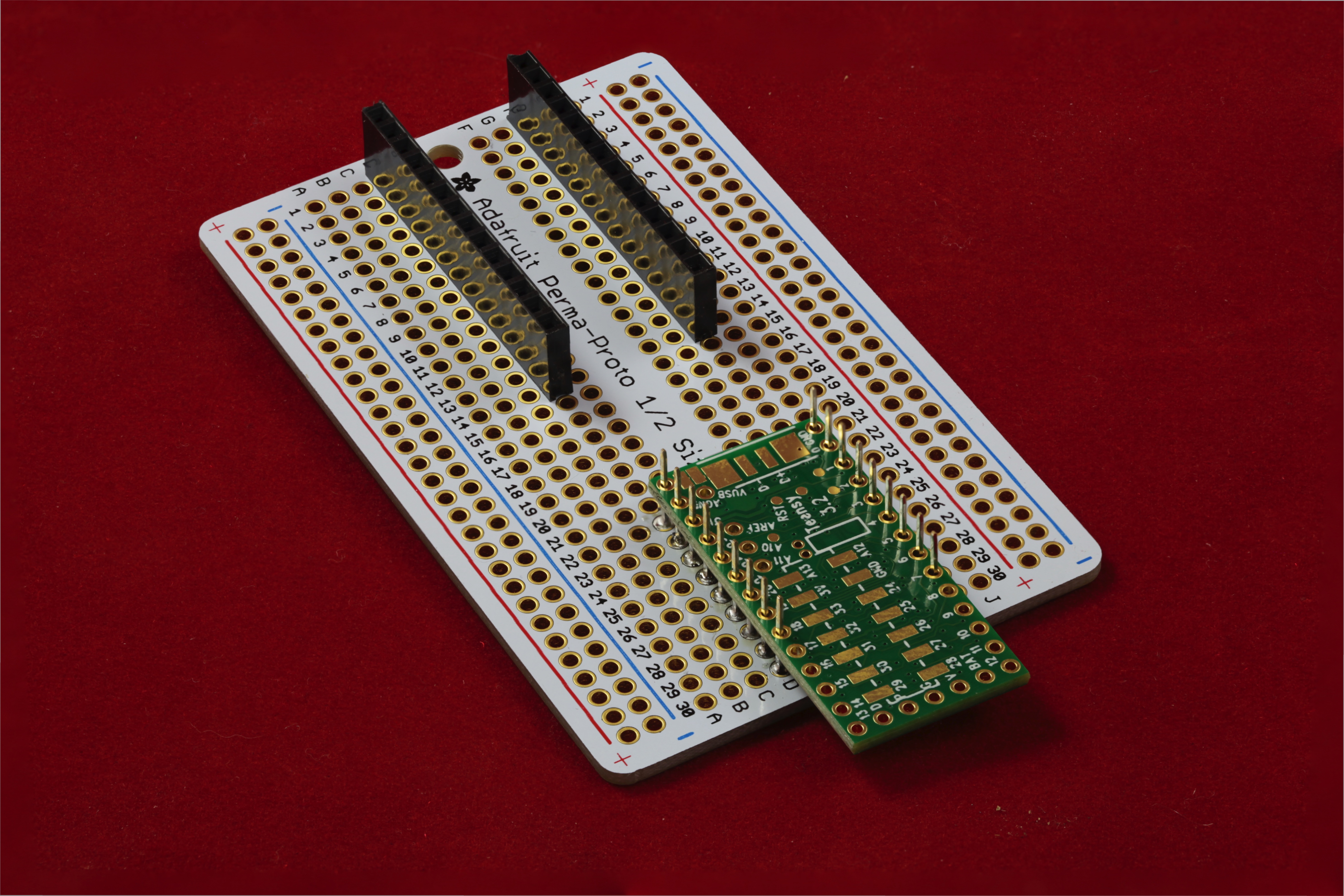
The next step is to solder the 14-pin female headers on the other side of the proto board. Again, they are 0.7" apart.
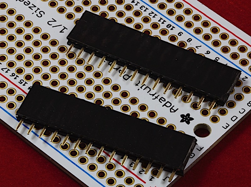
Once again I used a Teensy 3.2 with header pins to hold the headers in place while soldering them onto the proto board:
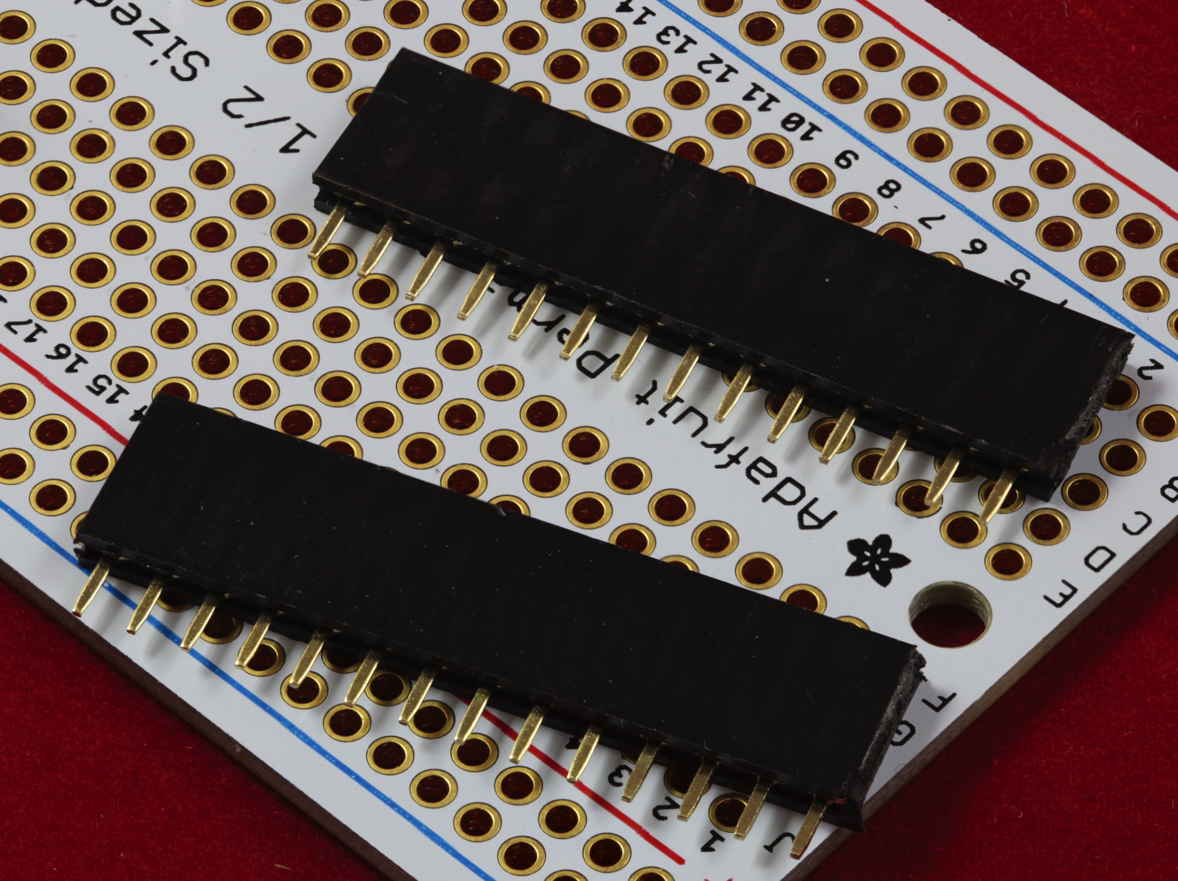
At this point, the jig assembly is complete. I usually install the three 8-pin headers on the two 9-pin male headers in order to protect the pins while in storage:
Assembling The Teensy 3.2
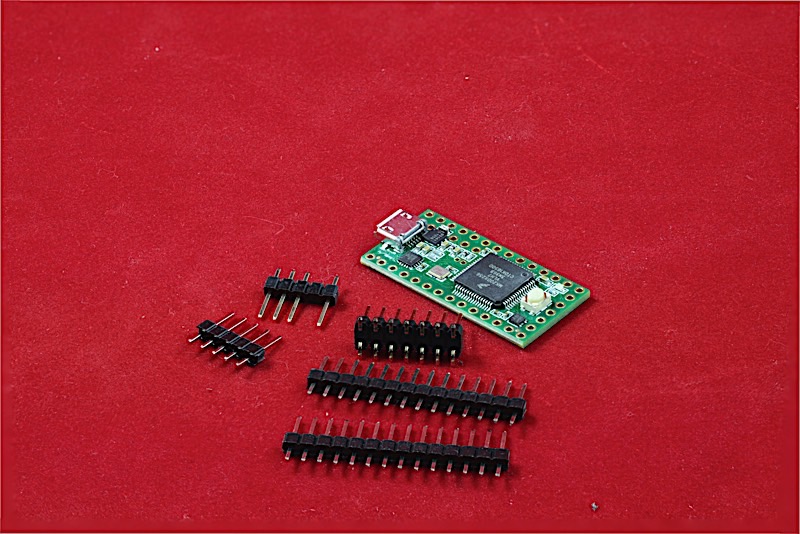
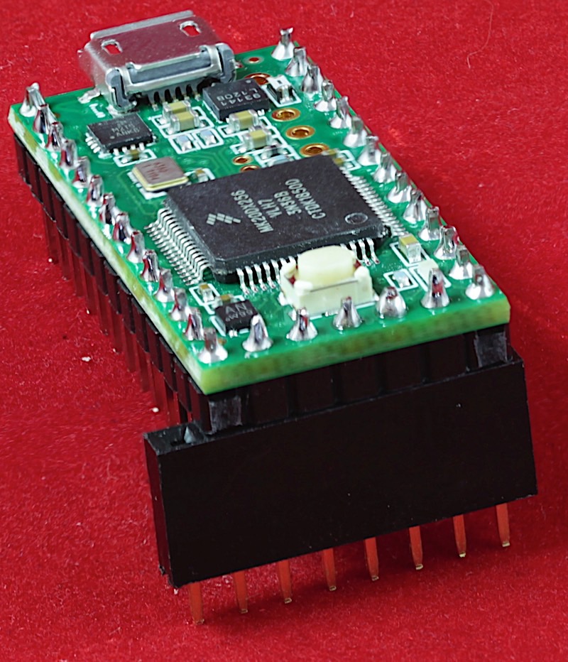
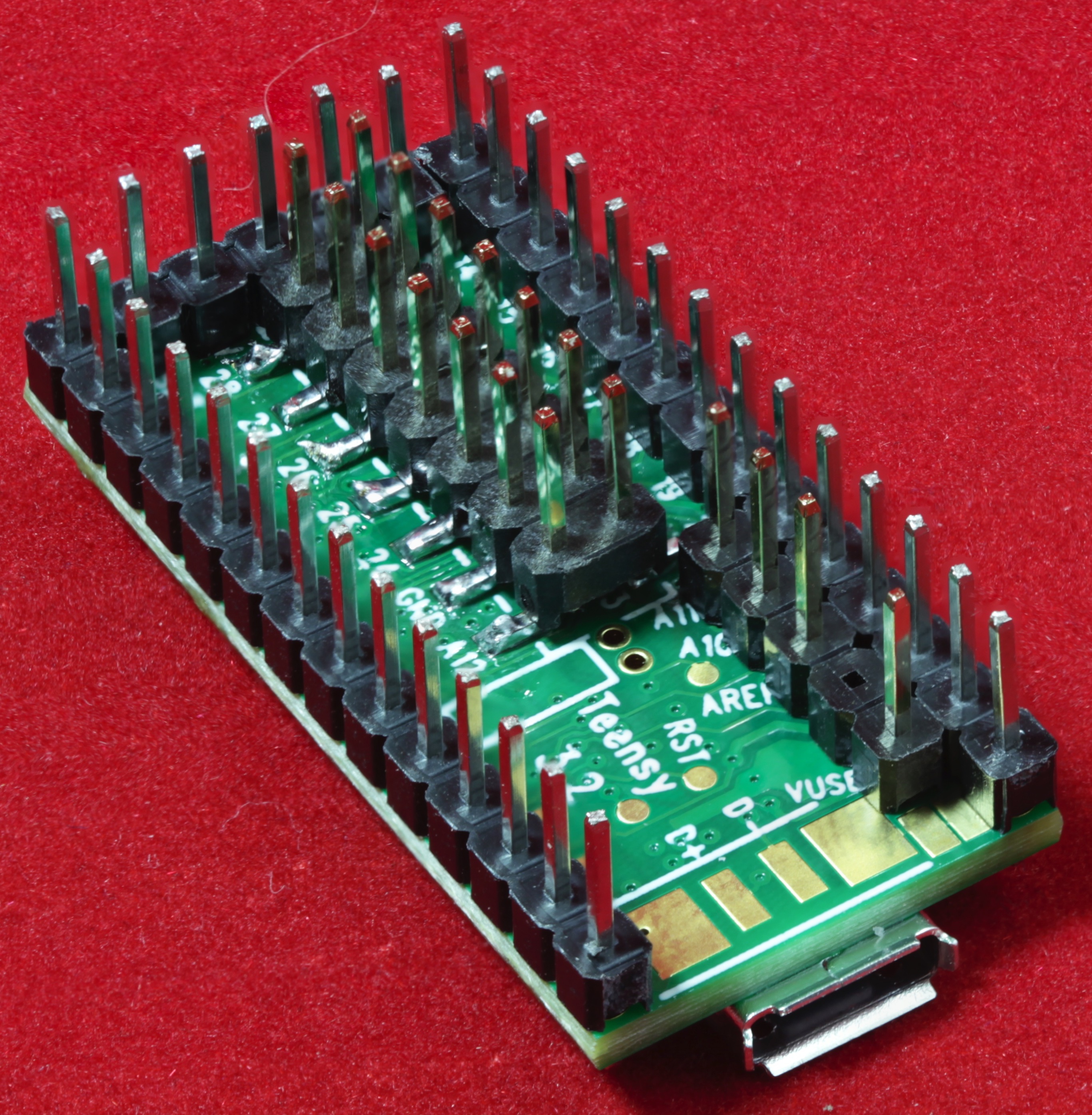
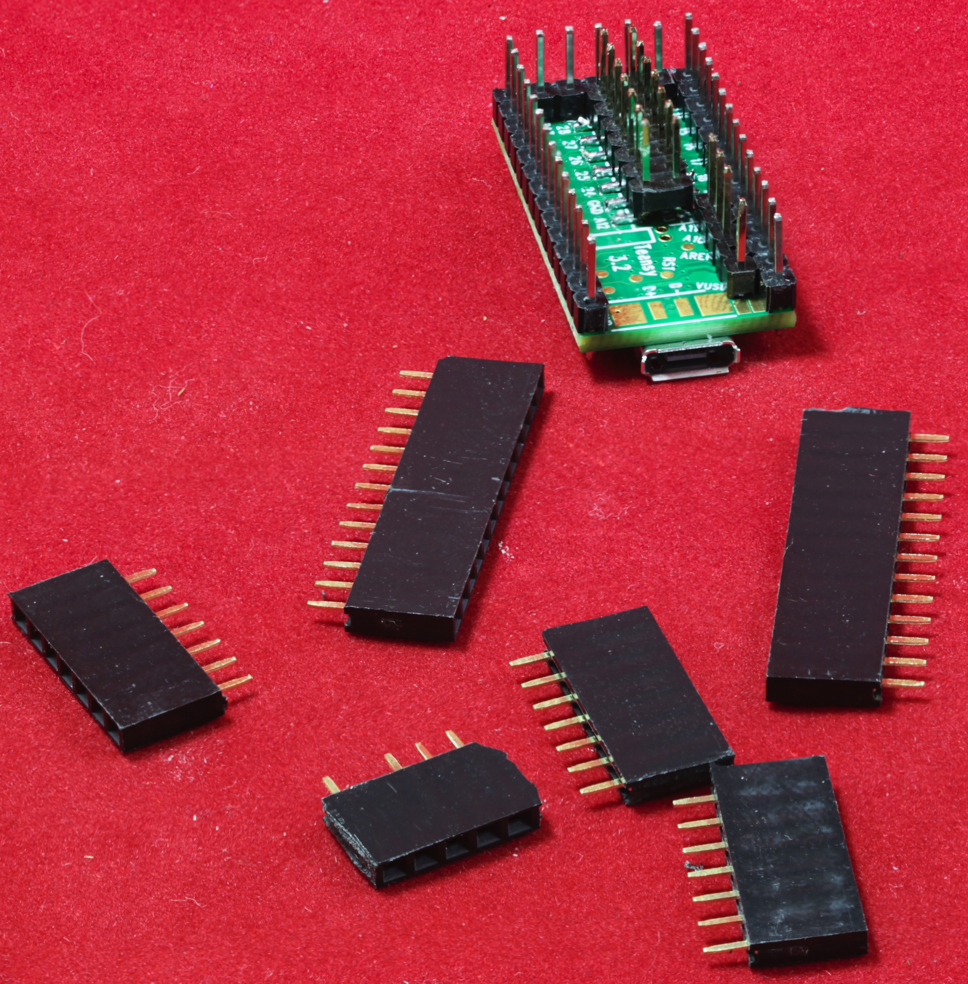
Now it’s time to actually put all the headers on the Teensy 3.2. For this process you will need a Teensy 3.2 (sans headers), a 2x7 SMT header, two 1x13 male headers, one 1x7 male header, and one 1x5 male header with pin 2 (or pin 4) removed:
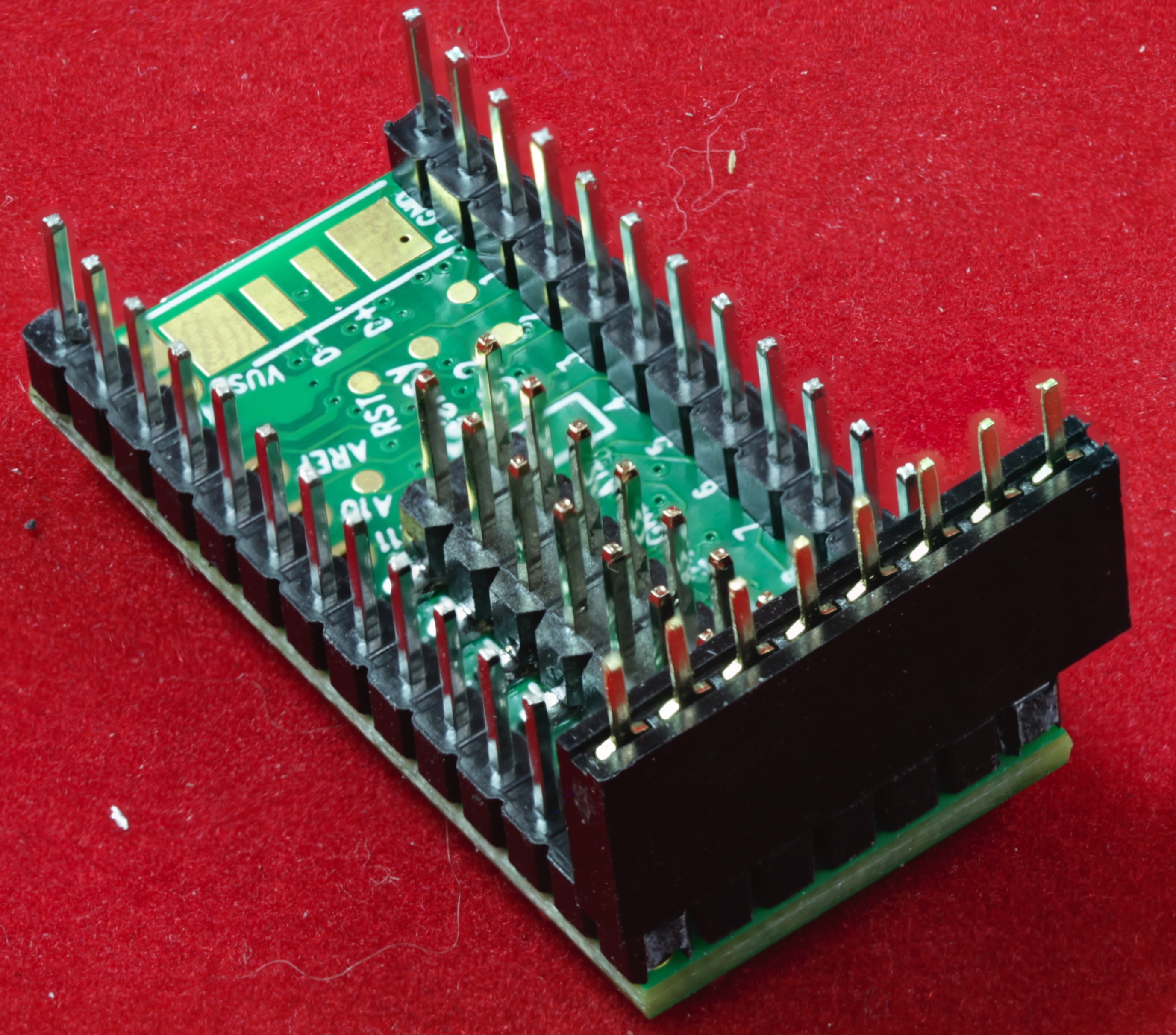
Begin by pulling off the three 8-pin female headers that are protecting the two 9-pin male headers and insert the Teensy 3.2 onto the headers (with the top of the Teensy facing down). Note that the headers should overlap only three of the SMT pads on the bottom of the Teensy 3.2:
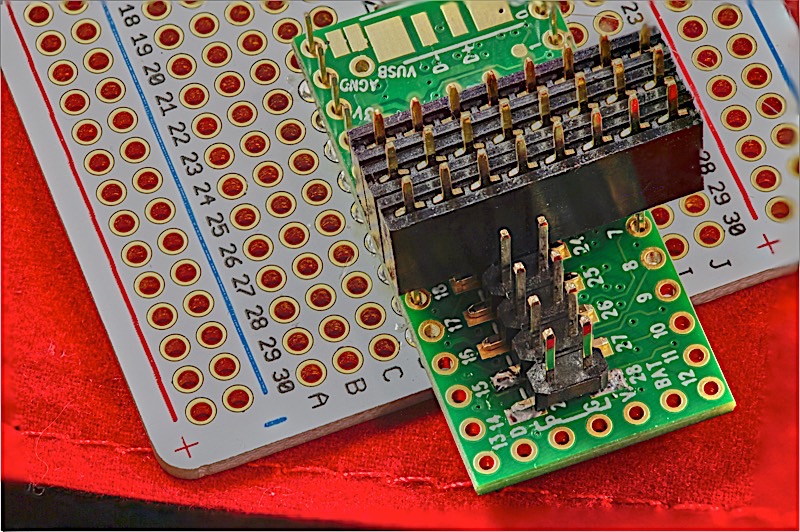
The next step is probably the most critical step of the whole process. Insert the SMT header in pins 2 and 3 on one of the 8-pin female headers. Repeat for the second and third 8-pin headers so that they are on one end of the SMT header. Gently insert the whole package on the three male pins coming through the Teensy so that the SMT header is aligned with the SMT pads on the Teensy 3.2. Note that the male pins are a bit short and will not form a tight bond with the female (8-pin) headers. This is okay, all they need to do is hold the SMT header in place long enough for you to tack 2-3 pins down onto the Teensy 3.2:
Tack (roughly solder) two or three pins of the SMT header onto the Teensy:
After tacking down three pins (at least on pin on both sides of the SMT header), remove the three female headers and remove the Teensy 3.2 from the jig:
Now finish soldering all the pins on the SMT header to the Teensy 3.2 pads. It wouldn't hurt to touch-up the tack job done on the first three pins if they need it:

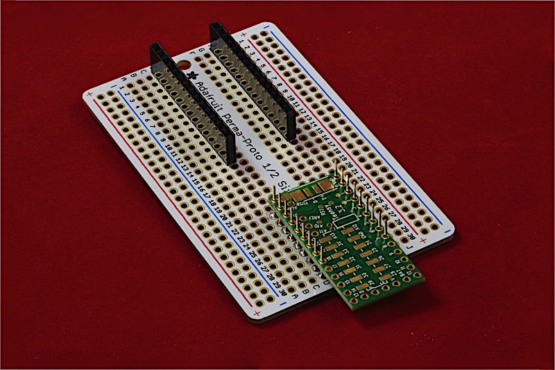
Insert the 1x14 male headers into the 1x14 female headers on the jig:
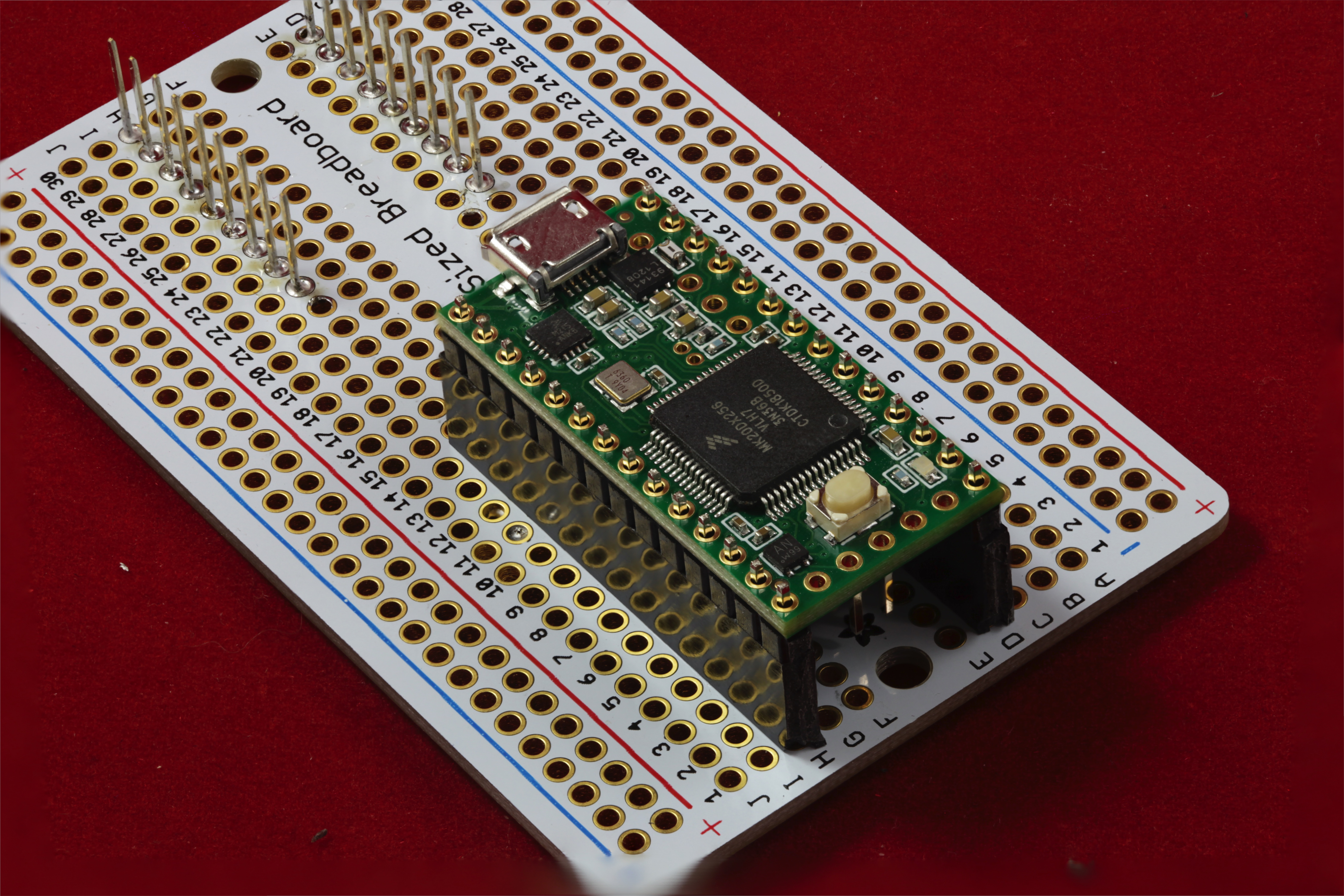
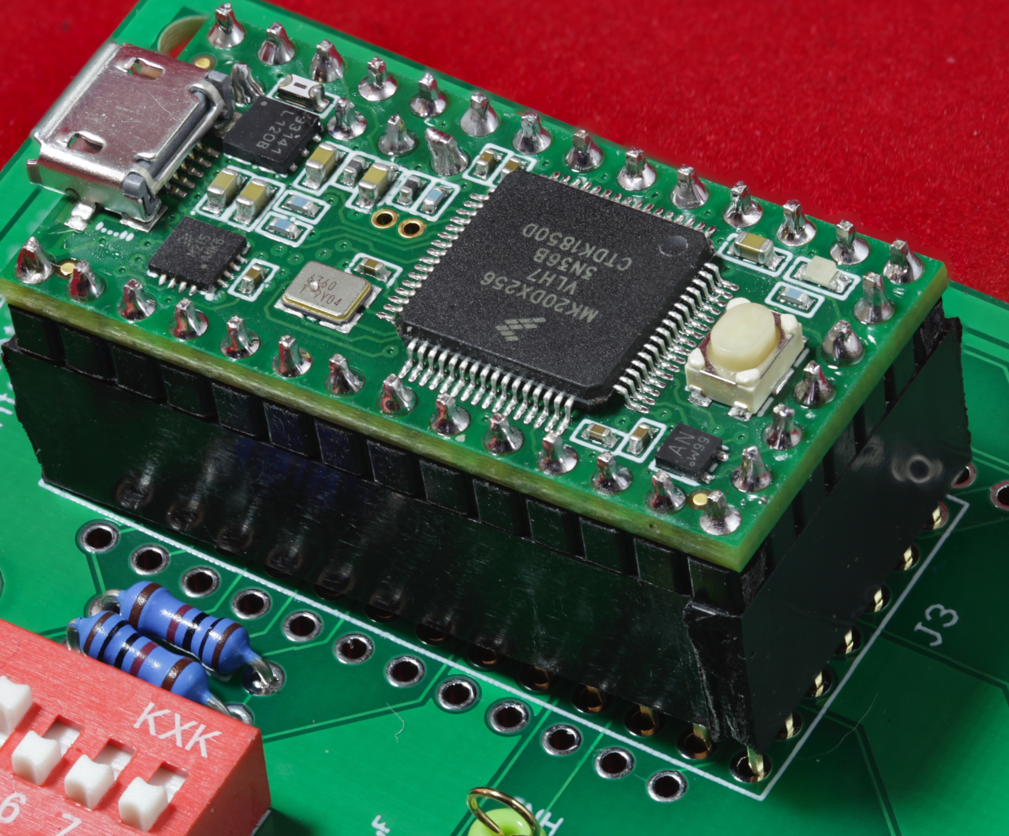
Now insert the Teensy 3.2 onto the 1x14 male headers:
Solder the 28 header pins to the Teensy 3.2. Warning: take care not to splash solder on other components or touch other components with the soldering iron (and desolder them).
The next step is to install the 1x5 male header across the bottom of the Teensy 3.2 PCB (this is the one with all five pins present). If necessary, trim a small amount of plastic off either end so that it fits in between the two 1x14 headers (use a hobby knife or wire snippers to do this). Align the header and hold it in place by putting one of the 1x8 female headers across the five pins (plus the two pins on the 1x14 headers):
Solder the five pins onto the Teensy 3.2:
Finally, insert the 4-pin male header into the remaining four holes and use two of the 8-pin female headers to hold it in place while you solder it:
And that completes soldering the headers onto the Teensy 3.2. Take the 1x8 female headers off the Teensy (and put them back on the jig to protect the male pins and to prevent them from getting lost).
Creating a Teensy Socket
Although I personally avoid sockets most of the time, I usually do install Teensy 3.2 SBCs in socket on PCBs I build. Despite the lack of reliability associated with sockets, I do this for a couple of reasons:
- Teensy 3.2 modules tend to be one of the more expensive devices on my circuit boards.
- Trying to remove a Teensy 3.2 from a PCB using a heat gun often damages the Teensy.
- If I mess up and forget to cut the VUSB trace, it's nearly impossible to cut it if the Teensy 3.2 is soldered to the PCB.
For these reasons, I usually socket my Teensies.
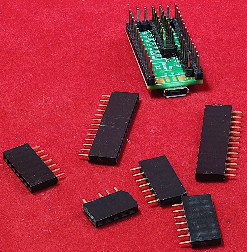
Of course, you can't buy an off-the-shelf socket for a Teensy 3.2. You have to build the socket yourself. Fortunately, Teensy 3.2 sockets are easy enough to manufacture from a pair of 1x13 female headers, three 1x7 female headers, a 1x6 female header and either a 2x6 or two 1x7 female headers (I usually construct these headers by chopping up 1x40 female headers, which are cheap and easy to find on Amazon).
The best time to construct a socket is right after you've soldered the pins on your Teensy and at the point in time you're installing the Teensy on the ultimate PCB (for example, this is one of the very last steps I usually do when assembling one of my PCBs that have a Teensy on them, such as the Teensy DAC, the Ethernet Watchdog Board, or one of the EtherPort boards).
The problem with constructing a Teensy socket is getting the Teensy (with header pins you've just soldered on) to fit in the socket. The solution is to construct the socket immediately after soldering the pins on the Teensy so you can use the Teensy as an assembly jig for the socket.
I typically install the 1x7 header on the bottom of the Teensy first. This is because the 1x13 and 1x7 headers (or 2x7, if you're using that) butt up against the 1x7. If you are using manufactured headers (not chopping up 1x40 headers like I do), there will be a snug fit when you install the 1x13 and 1x7 (2x7) headers against the 1x7, but they should fit fine. If you're chopping up headers, I recommend using the original ends of the 1x40 headers for the 1x13 and 1x7 headers that butt up against the 1x7. The 1x7 and 1x5 headers don't require smooth ends as they don't butt up against anything. Note that on the 1x5 header you will have to pull out a pin (from position 2 or 4) with a pair of needle-nose pliers; while there won't be a problem inserting the 1x5 on the Teensy with that pin in place, there probably won't be a hole on the PCB to accept it later.
The next step is to insert the Teensy/headers into the holes on your PCB. I usually find that the 1x7 header has the biggest problem going into its holes on the board; this is because the other headers (1x13 and 1x7/2x7) are pressing against it and they cause it to shift a small amount).
Typically, dragging a hobby knife or flat-blade screwdriver along the pins is all it takes to bend them enough to go into the holes.
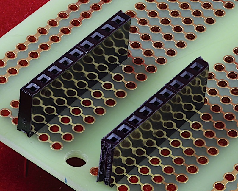
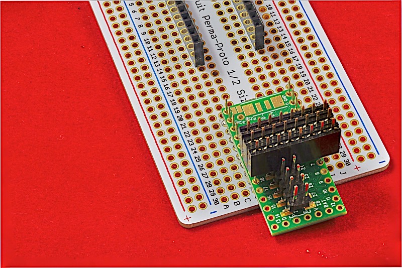
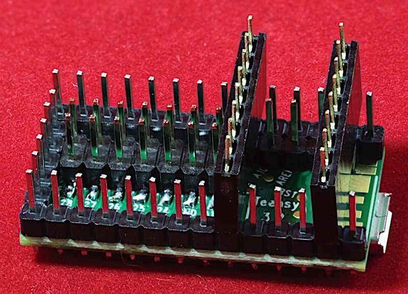
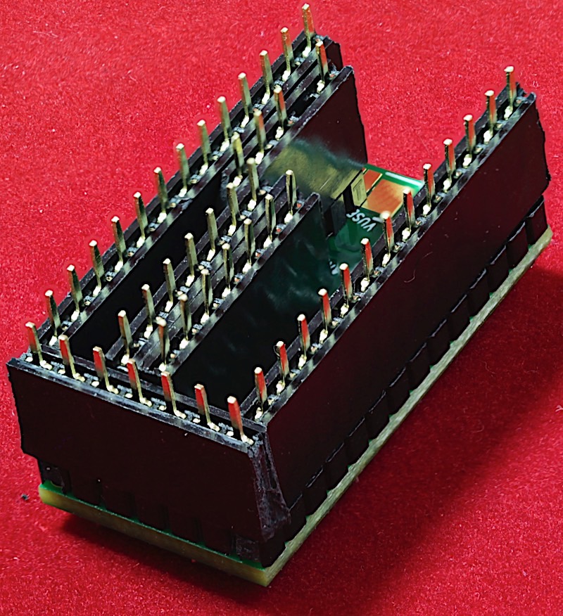
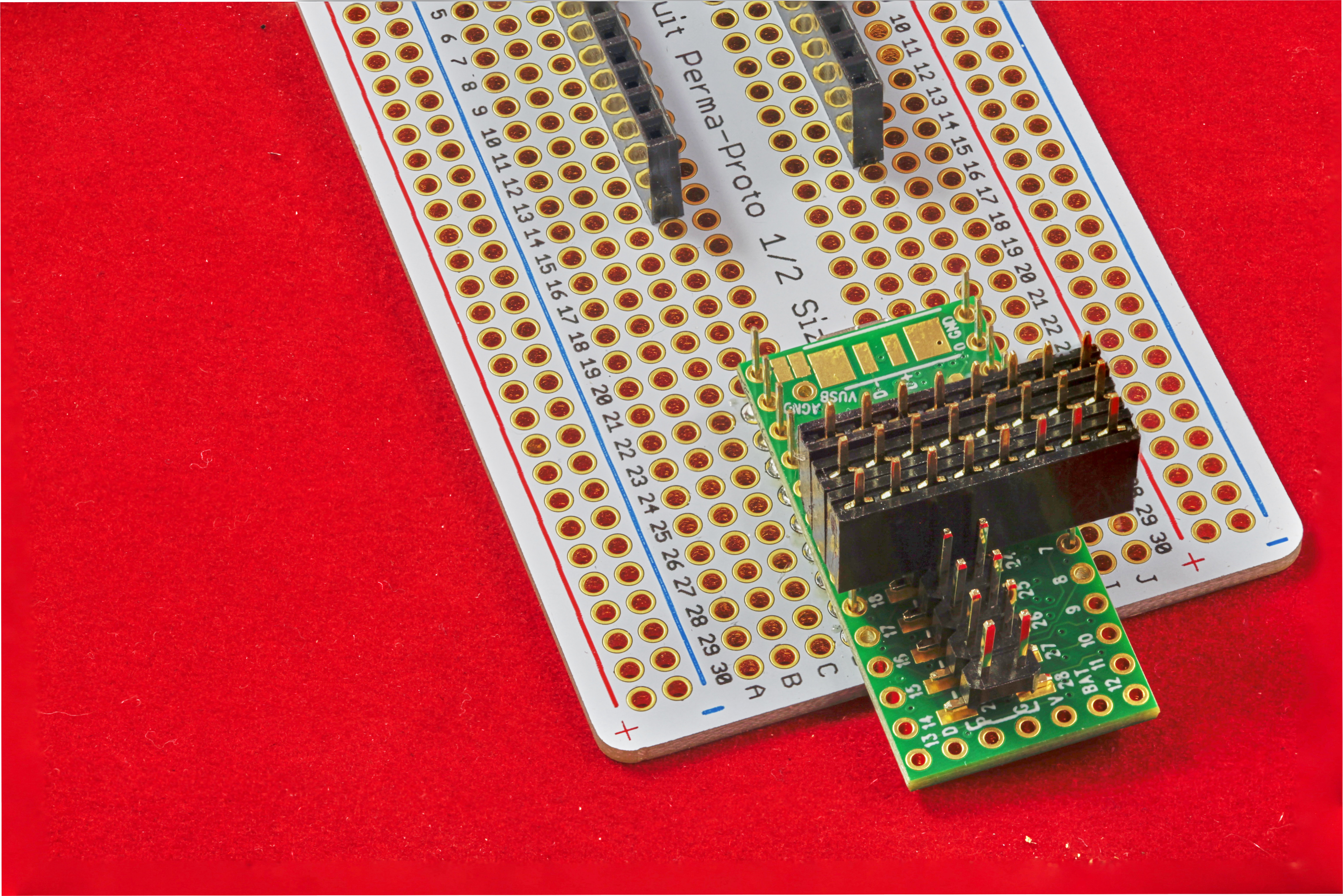
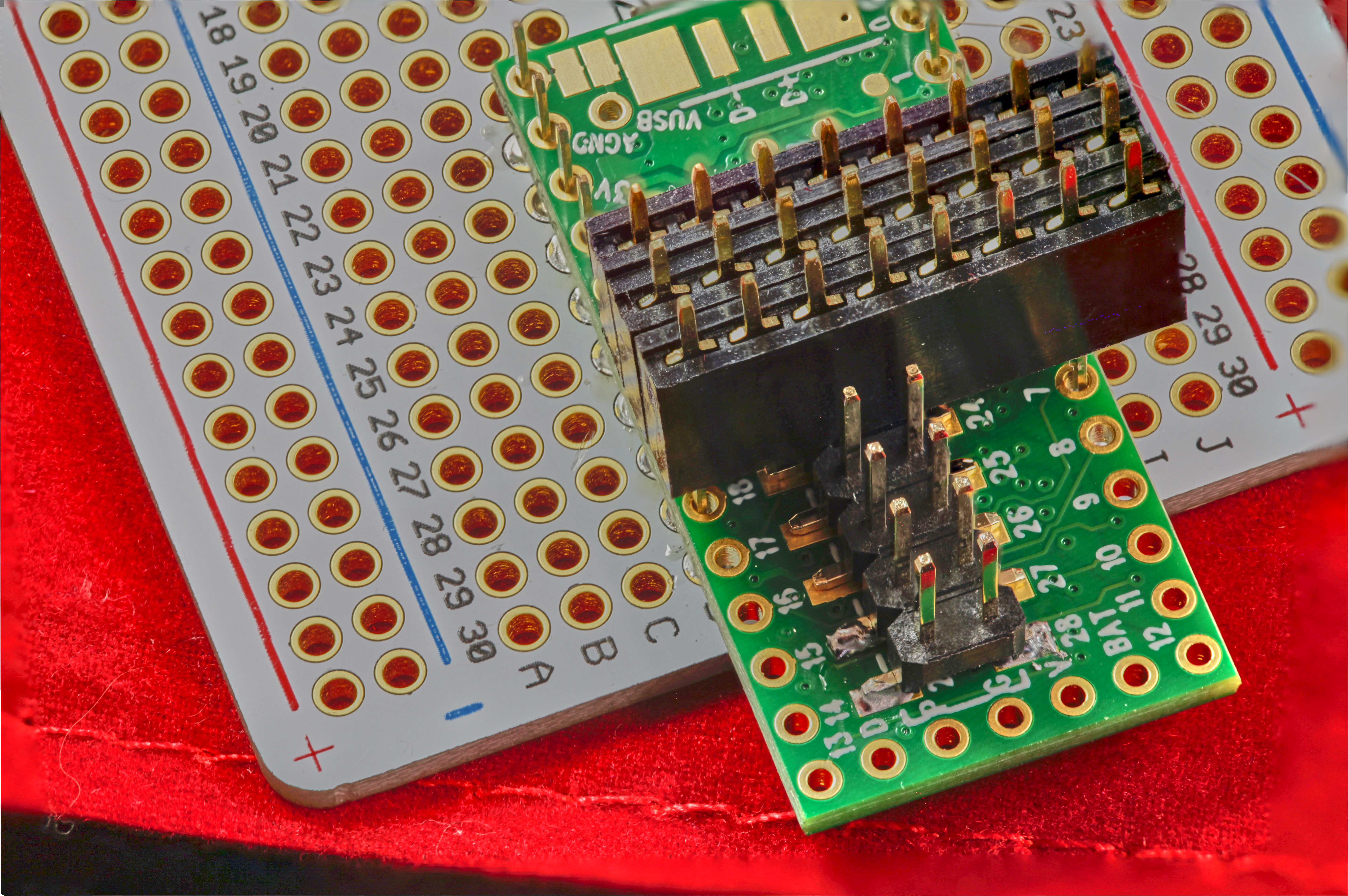
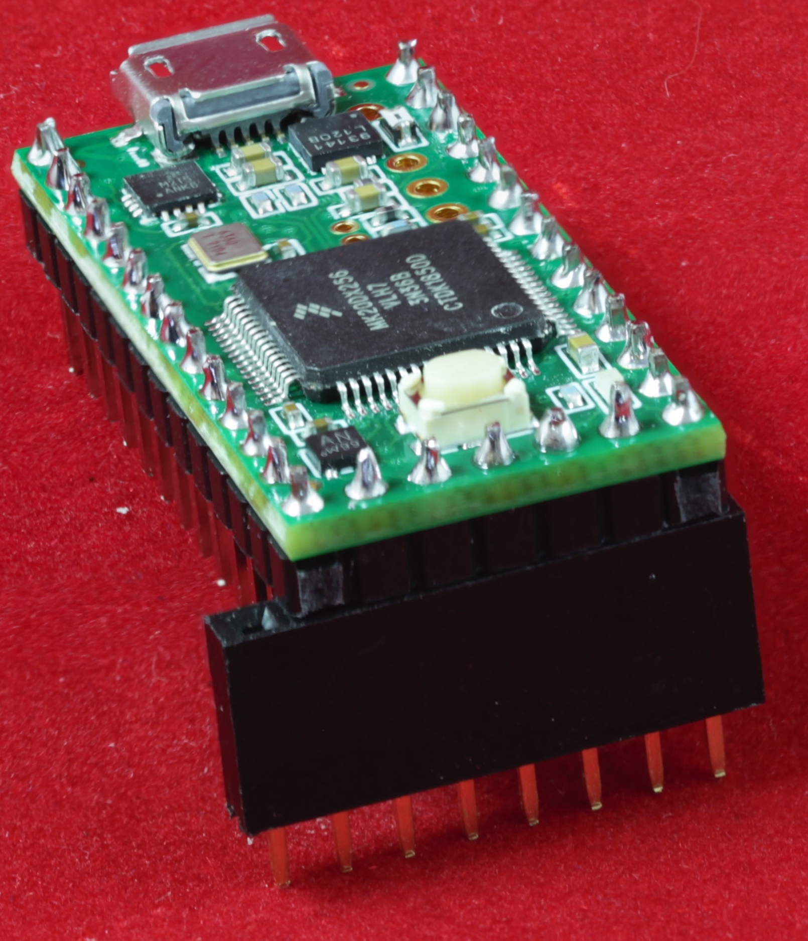
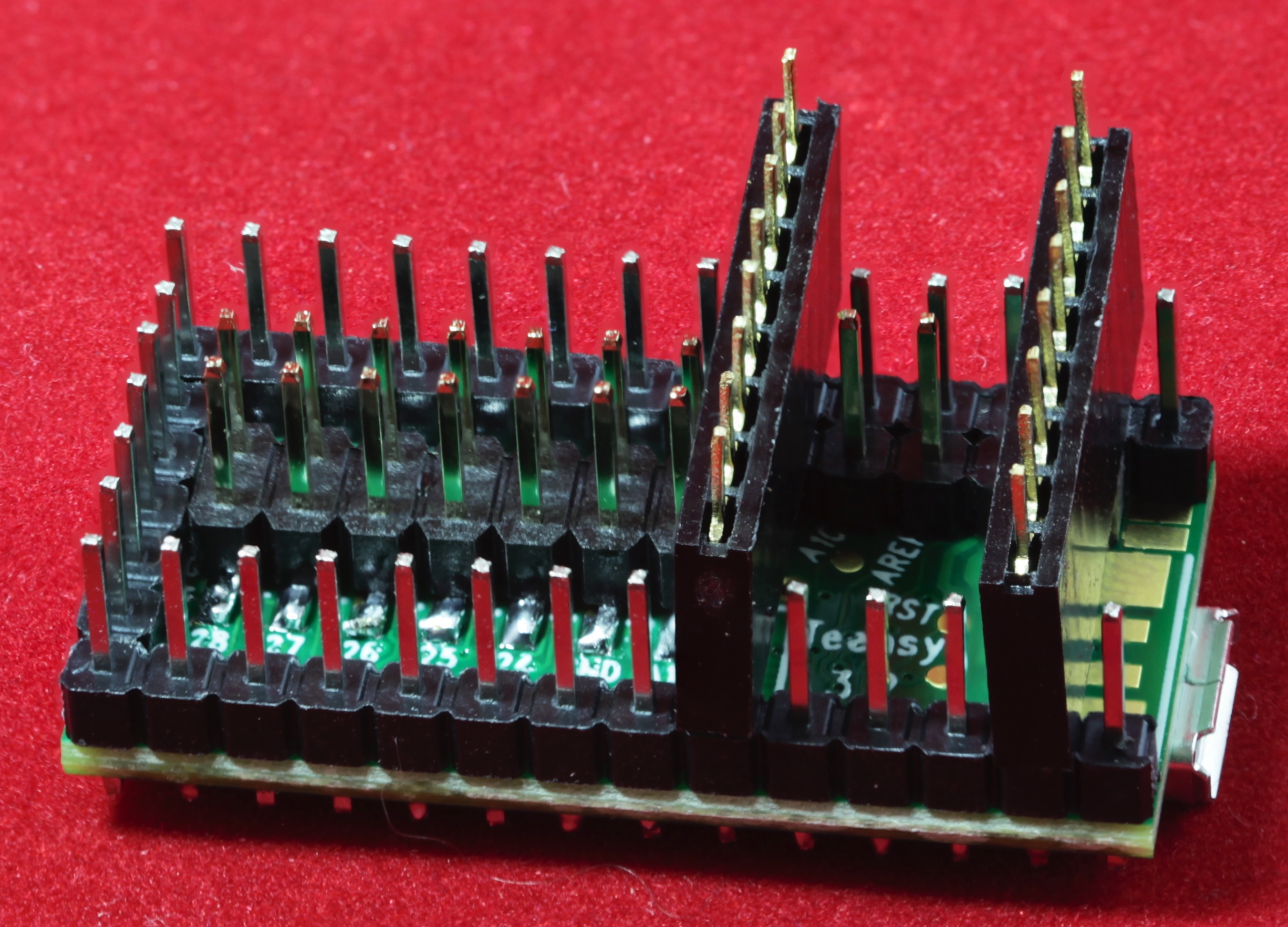
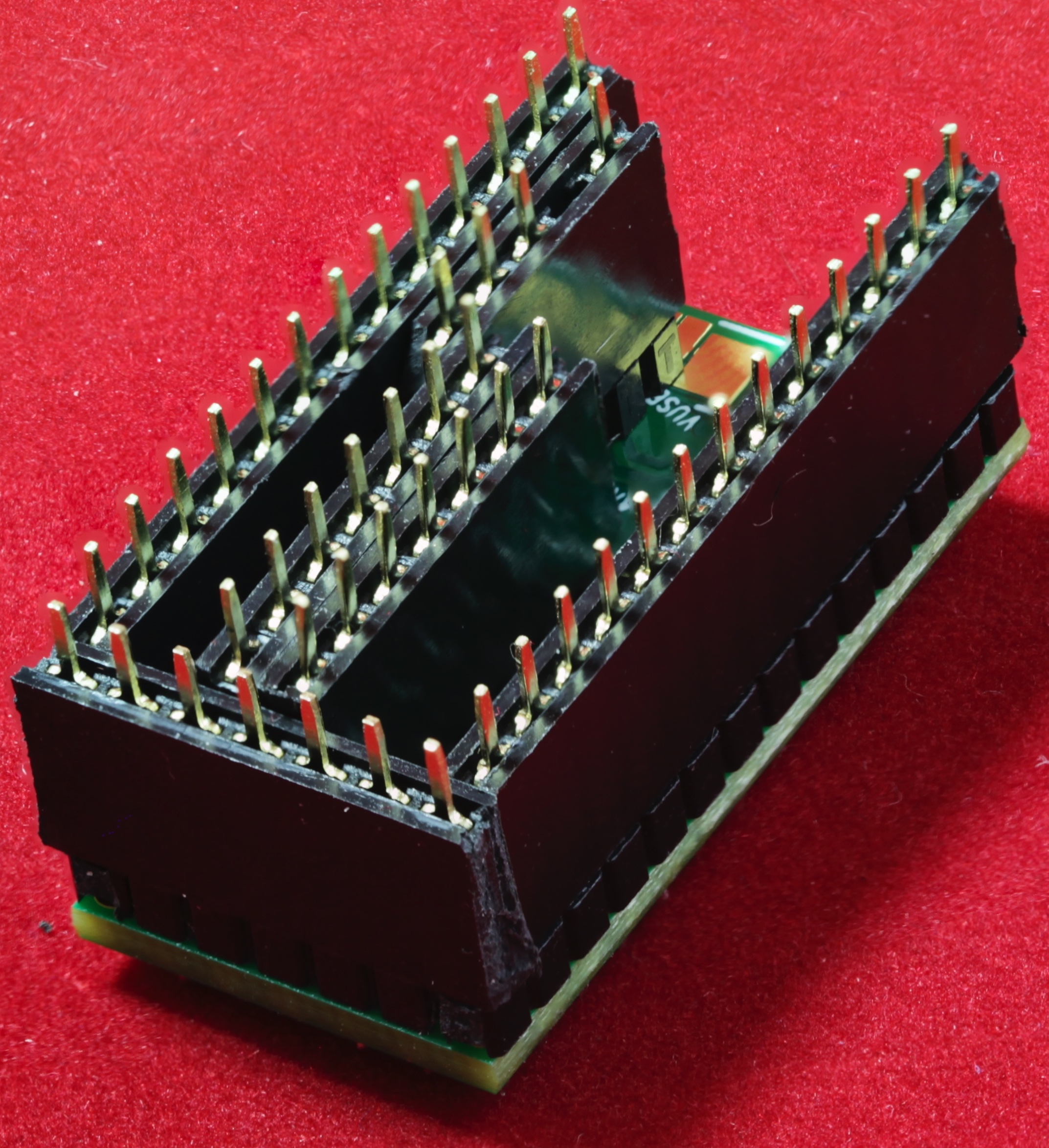
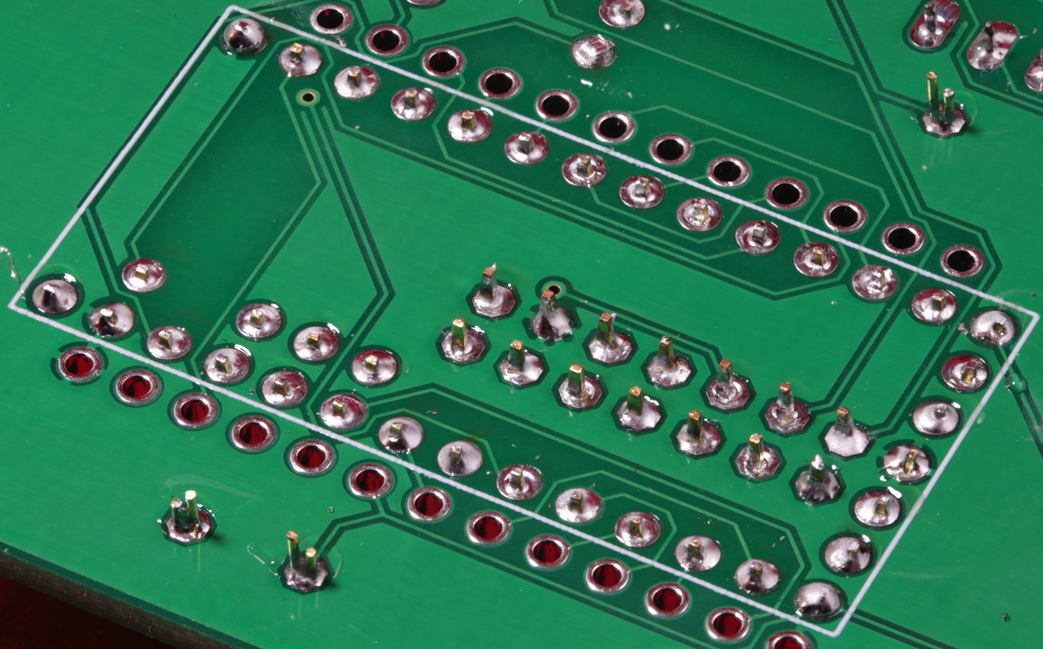
Once all the pins are in the holes, turn the board over and while pressing the Teensy 3.2 in, quick tack down a couple of pins on the 1x7 header and the corner pins on the other headers. Note that the SMT header (the 2x7) on the Teensy rides higher on the PCB that the other headers due to the nature of the SMT connection. Therefore, the two 1x7 headers that the SMT header plugs into will bottom out on the PCB before the other headers do. As you can see in the picture below, their pins stick out farther than the pins on the other headers.

Because of the height difference, the headers will "rock" a little from side to side. When tacking down the pins, be sure to hold the Teensy as level as possible (for aesthetic reasons, structurally and electrically it won't make much difference).
After tacking down the corners and verifying that you're happy with the socket alignment, solder all the remaining pins.
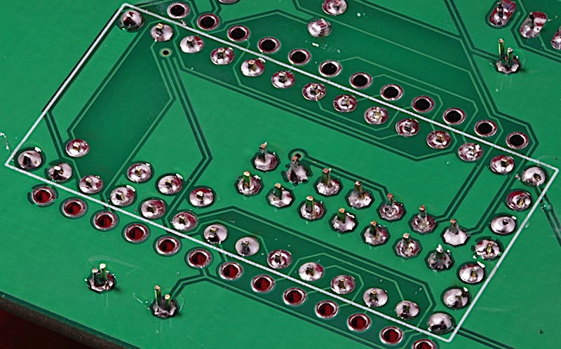
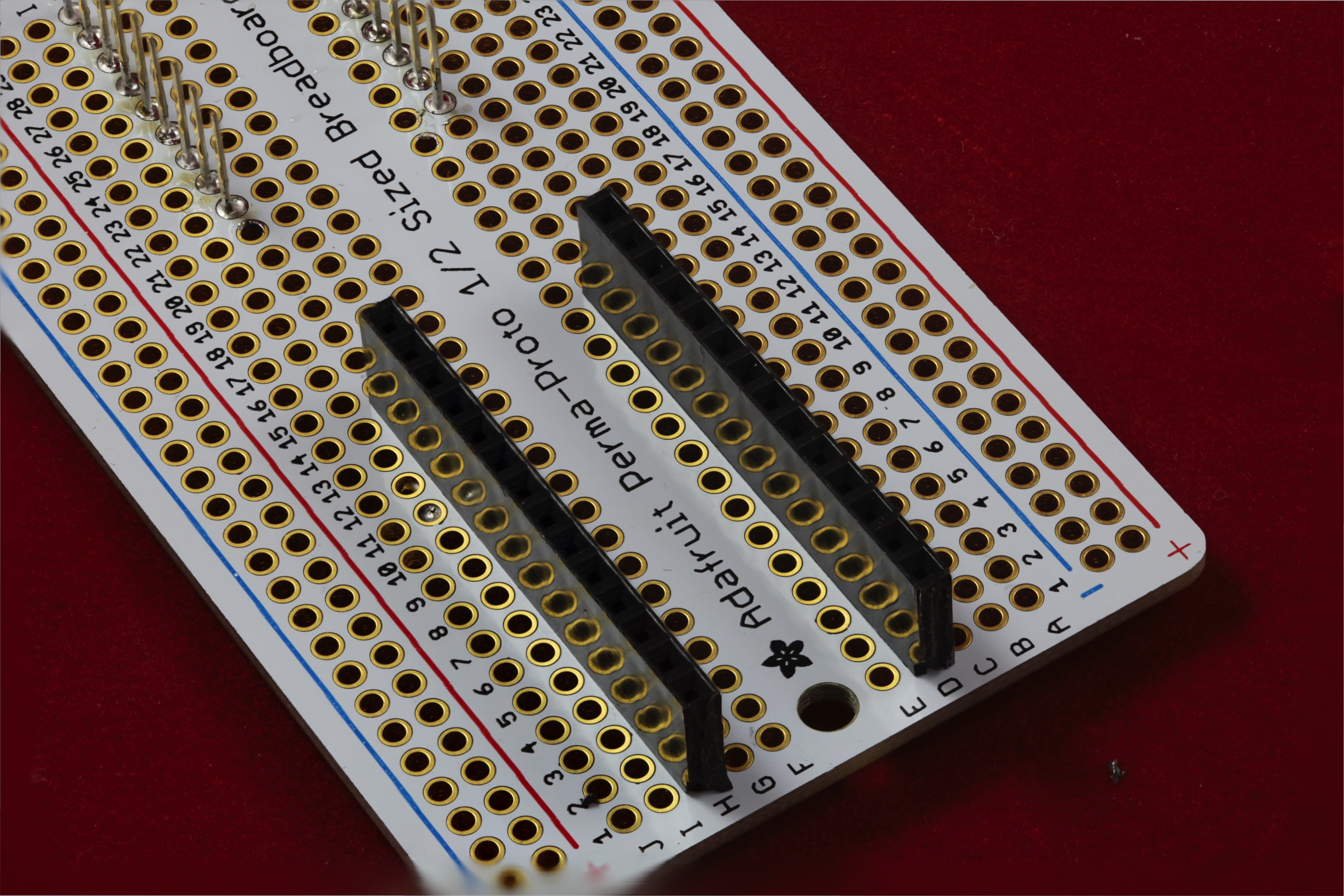
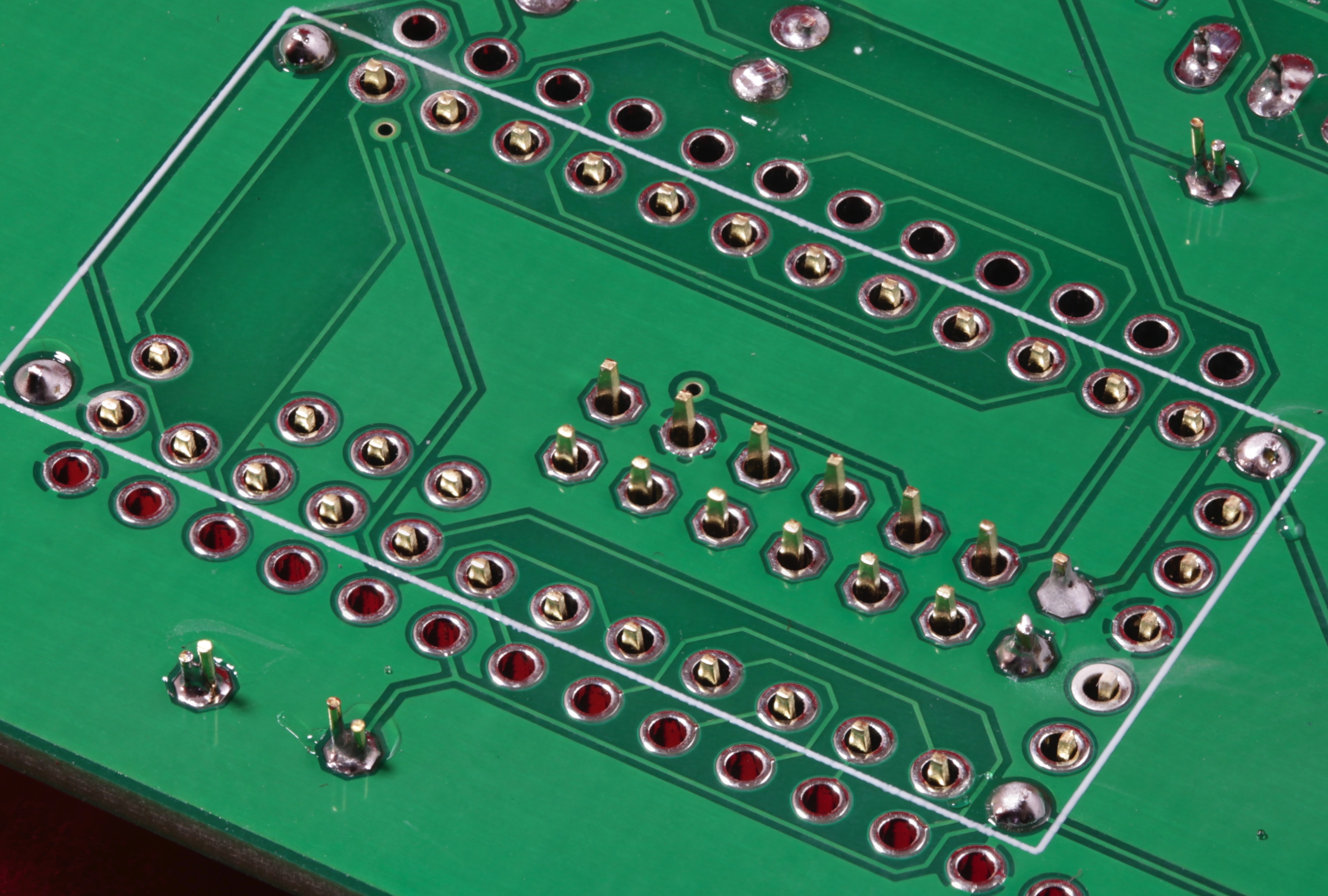
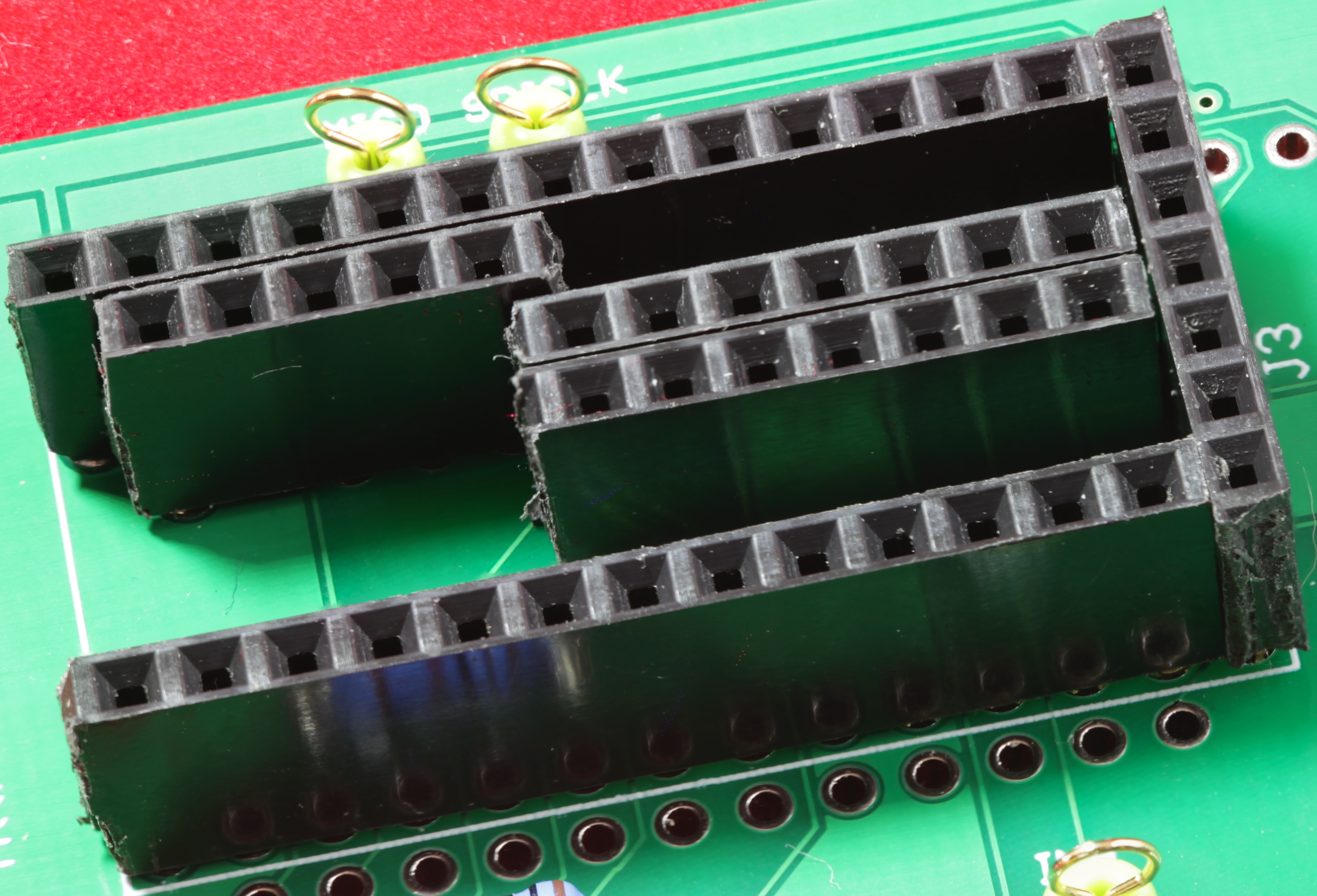
At this point, your socket should be properly installed. Here's what it looks like with the Teensy 3.2 removed:

Warning: The socket has a (very) limited insertion/removal lifetime. Each time you insert or remove a Teensy 3.2 into/from this socket, you increase the likelihood of reliability issues. The purpose of the socket is to allow you to easily remove the Teensy 3.2 (the most expensive component on the board and the one most difficult to remove) if the board does not work properly. This socket is not intended as a device to allow you to share the Teensy 3.2 amongst several different devices by swapping it around, as needed. Typically, you would not remove the Teensy 3.2 after soldering the socket onto the PCB (I only did it in the example above to take a picture of the socket).