
Note: All photographs appearing on this page are freely usable for any purpose. Links to high-resolution versions of the pictures appear below each picture.
Digital Data Acquisition & Control System
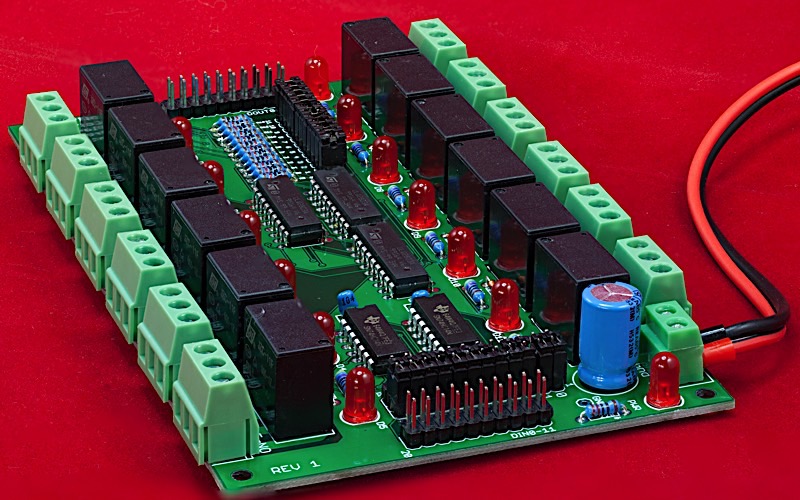
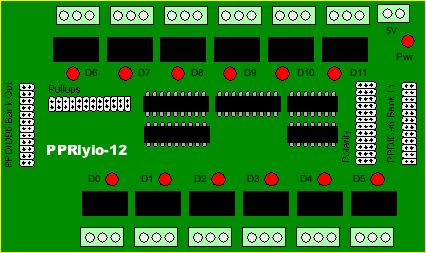
PPRlyio-12
12-Channel mechanical relay input/output board
High-resolution image shot with a Canon EOS 5D MII
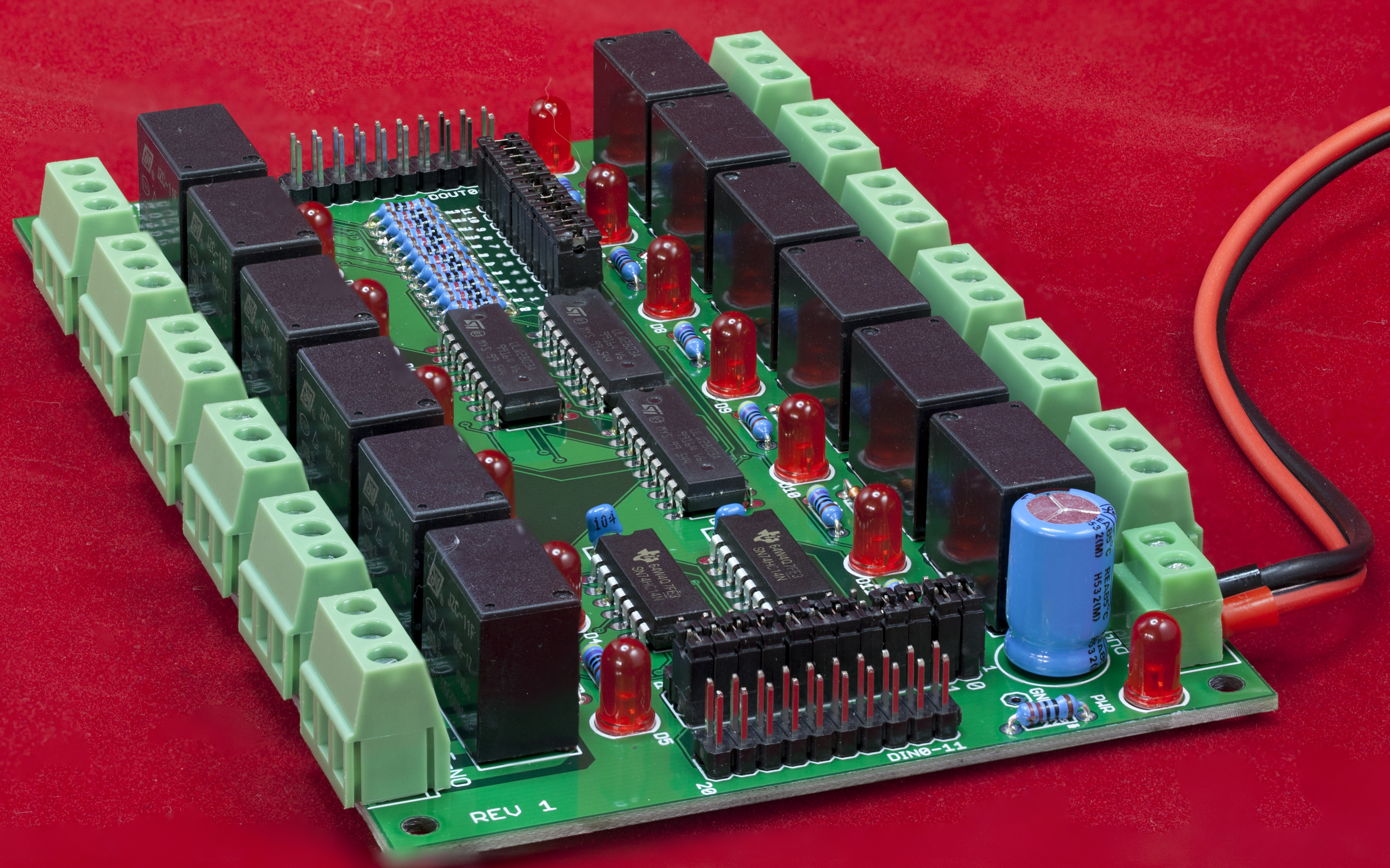
The PPRlyio-12 board is a 12-channel digital I/O board featuring 12 mechanical relays. It normally connects to the PPDIO96 board via one of the bank connectors. The PPRlyio-12 has the following features:
- Open Hardware design based on Creative Commons 4.0 license
- Single 5V power supply input connector (screw terminals)
- LED indicates when power is applied
- 12 independent digital input or output channels featuring high-amperage relays (rated at 5 amps each, though the board allows 2A per relay)
- 12 LEDs indicate the current state of each relay channel
- 12 three-pin screw terminal output connectors with NO (normally open), COM (common), and NC (normally closed) contacts
- TTL-level inputs (add a PPOpto-12 board to support dry contact inputs and provide opto-isolation)
- Jumper-selectable polarity (active high or low) on all input pins
- Jumper-selectable pull-up resistors on all output pins (Open Collector or TTL-compatible outputs)
- Relays provide isolation from the digital input and output connectors
- (2) PPDIO96-bank-compatible ribbon cable connectors (20-pin) -- one for input and one for output
- Schematic and board layout are available in Eagle format
- DIN rail mounts allow the board to be optionally mounted in a horizontal orientation on a 35mm DIN rail
- DIN rail brackets are available in .STL format for 3D-printing
- Full documentation including System Requirements Specifications (SyRS), Hardware Requirements Specifications (HRS), Hardware Inspection list (HI), Hardware Test Cases (HTC), Hardware Test Procedures (HTP), Hardware Design Description (HDD), and (reverse) Traceability Matrix (RTM) are available for the DAQ system, including this board.
Bill of Materials (BOM) for the PPRlyio-12 board:
- (12) 3-pin screw terminals (5mm/0.2" centers)
- (12) JCZ-11F 005-1Z 5VDC relays
- (13) 5mm LEDs
- (12) 1N4148 diodes
- (12) 470 Ω resistors
- (12) 10kΩ resistors
- (1) 220 Ω resistor
- (2) 0.1 µF decoupling capacitor
- (3) ULN2803 8-channel darlington buffers
- (2) 74HC04 hex inverting buffer
- (1) 2-pin screw terminal (5mm/0.2" centers)
- (1) 24-pin (2x12) male header
- (2) 20-pin (2x10) male headers
- (1) 36-pin (3x12) male header
- (1) PPRlyio-12 PCB
- Optional: (1) 1000 µF decoupling capacitor
- Optional: (1) test pin
- Optional: one set of horizontal 35mm DIN rail mounts for DAQ boards
Note: If you only want a few PPRlyio-12 PCBs, contact Plantation Productions (randy@plantation-productions.com) to see if there are any in stock. Bare boards are $25 each plus shipping; fully assembled and tested boards are $350 each. If you need more than a couple and you're not in a huge hurry, it costs about $150 (plus about 4-6 weeks) to have a set of 10 manufactured and shipped to you from China. I use Seeed Studio Fusion PCD service (https://www.seeedstudio.com/fusion.html). The PPRlyio-12 PCBs are four-layer boards. Here are the Gerber files for them (provide these files to Seeed Studio or your personal PCB manufacturer).
PPRlyio-12 Gerber Files for PCB
If you want to modify or enhance the PPRlyio-12 design, or re-layout the PCB using Eagle, here are the Eagle files:
PPRlyio-12 Eagle files (Schematic and board layout)
If you simply want to view the schematic on-line, you'll find that here:
The DIN rails were created using AutoDesk's Fusion 360 (to produce STL files) and I personally print the results on a Lulzbot Taz6 3D printer using ABS filament (ABS is recommended for this job, PLA and PETG are a bit brittle). The STL files can be found here:
PPRlyio-12 DIN Rail Brackets 3D printer files
PPRlyio-12 Board Layout
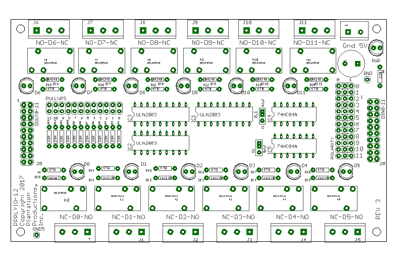
I/O Connections on the PPRlyio-12 Board
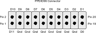
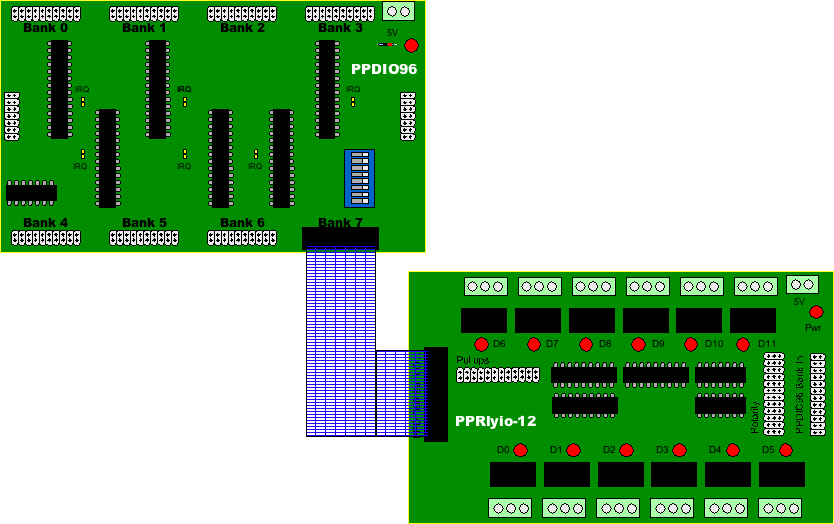
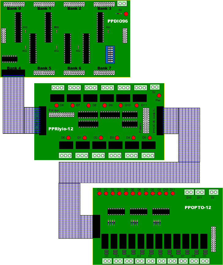
The PPRlyio-12 board contains two sets of 20-pin headers (ribbon cable connections) that are compatible with the PPDIO96 bank connections (12-channel digital I/O). Each PPRlyio-12 board contains an input connector (on the left-hand side of the board) and an output connector (on the right-hand side of the board):
Both input and output (20-pin) connectors have the following pin-out:
The PPRlyio-12 board can operate in one of three modes: input (to the PPDIO96), output (from the PPDIO96), or as a standalone board. Later sections will describe these three modes.
Important!
All inputs to the PPRlyio-12 board must be tied high (+5V) or low (Gnd/0V). If you leave an input floating, this may cause the signal to oscillate; this could result in the relay constantly turning on and off which will damage the relay (by rapidly wearing it out). Any unused inputs should be tied to ground and their polarity (see the section on polarity a little later) set to '1'.
Pullup Resistors
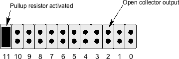
There is a 24-pin header (2x12) labeled "Pullups" on the PPRlyio-12 board. Each pair of pins (vertical orientation) allows you to add a pullup resistor on each output channel on the board. Without a jumper present, the corresponding output pin operates in "open collector" mode (driven by one output pin from a ULN2308 Darlington array package). In this mode, the corresponding output pin looks like a switch to ground that is closed with the input signal is active high.
By installing a jumper to the circuit, you add a pullup resistor to the output on the ULN2308. The produces a TTL-compatible signal (+5V) on the output pin when the input signal is low, it pulls the signal to ground when the input signal is active high (i.e., it inverts the input signal).
Each ULN2308 Darlington channel is capable of sinking as much as 500 mA. The supplied 10kΩ pullup resistors (when the corresponding jumper is installed) only produce 0.5 mA @ 5V. Here is the data sheet for the ULN2308 darlington array:
Input Polarity
There is a 36-pin header (3x12) labeled "Polarity" on the PPRlyio-12 board. A jumper across two of the three pins in each row selects either "active high" or "active low" polarity for the input signal. If a jumper is across the left-most two pins, then that particular input channel will assume an active low input signal; if a jumper is across the right-most pair of pins, then that channel will assume the use of an active high input signal.
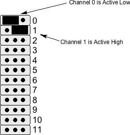
By allowing an inversion of the input polarity, it is possible to ensure that the relays are in a consistent state when power is off and when power is applied and the input signal is in an active state. For example, the PPRlyio-12 board was originally designed to handle SCRAM inputs for a nuclear reactor. When power is not applied to the board, you want the "SCRAM loop" to be broken (or "open circuit"). To achieve this, you would want to wire the SCRAM loop through the normally open contacts on the relay. This way, when power is not applied to the circuit the natural position of the relay is "open" and the SCRAM loop is broken. When power is applied to the system, an inactive SCRAM input should result in a closed relay and an active SCRAM input should result in an open relay. Assuming an active high signal, this means that a logic '1' input should result in an open relay (and a logic '0' input should result in a closed relay). To make this happen, you'd need to invert the logic controlling the relay. This is easily achieved by inverting the input SCRAM signal (by putting the jumper on the left-most two pins on the polarity header for the specific channel).
Relay Connections
The contacts on each of the 12 relays on the PPRlyio-12 board are routed to a 3-pin screw terminal block. These pins are the Normally Open (NO), Common (COM), and Normally Closed (NC) contacts. The relays themselves (JCZ-11F 005-1Z 5VDC) are rated for 5A operation. In practice, of course, you do not operate an electronic device at its absolute maximum rated value. Good engineering practice suggests that you derate a device by 50%. Therefore 2.5A is a more reasonable choice the maximum current you should put through one of these relays. The PPRlyio-12 board has 100 mil traces (top and bottom layers) from the relay contacts to the associated screw terminal pins. Therefore, it is probably safe to run these guys with as much as 2.0-2.5 amps without worrying about the PCB heating up too much.
By their design, mechanical relays offer a fair amount of isolation beween the relay contacts and the rest of the circuit. However, PPRlyio-12 boards are rated for 30VDC at the relay contacts. While the relays themselves are rated for 125VAC, putting such voltages directly on the PPRlyio-12 board is unsafe. Furthermore, if any high voltage transients occur on the relay contacts, you may get arcing between traces on the PCB. If you need to handle higher voltages, use the relay contacts to actuate a separate relay (far away from the PPRlyio-12 board) to switch the actual voltage.
The PPRlyio-12 board uses JCZ-11F-05VDC relays. Here's the datasheet for those relays:
JZC-11F-05VDC relay data sheet
Operation as an Input Device
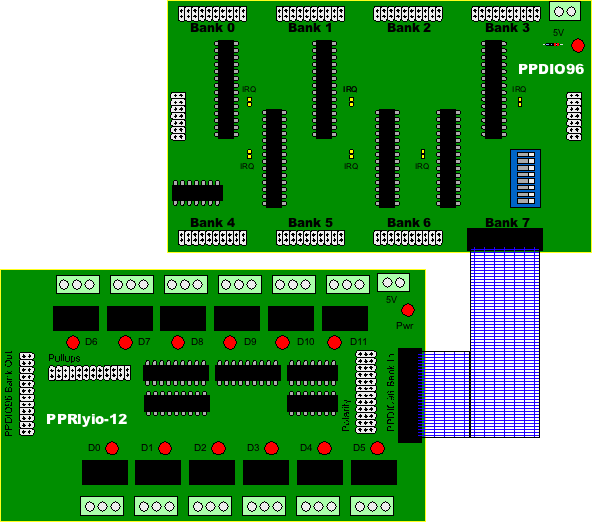
By connecting the PPRlyio-12 output connector to one of the bank connectors on a PPDIO96 board, you can use the PPRlyio-12 board as an input device. The PPRlyio-12 board will buffer the 12 input signals and pass them along to the PPDIO96 board.
Because of the nature of the ULN2308 Darlington transistor array devices, the PPRlyio-12 board will invert the signal as it passes through the board. However, the MCP23S17 GPIO expansion chips that the PPDIO96 uses provide a polarity register that will automatically re-inverts the signal (or you could just invert the signal yourself in software when reading the data from the PPDIO96).
Note that you do not use the polarity header to invert the output signal being fed to the PPDIO96 board. If you invert the polarity on the polarity header, this will invert the signal sent to the relay as well as the output connector. Of course, you can always use the polarity jumpers and then swap between the NC (normally closed) and NO (normally open) contacts to invert the signal. However, this scheme may fail if you're trying to create a fail-safe system (see the discussion above on polarity).
The main reason for operating a PPRlyio-12 in input mode is because you want to control a relay from a TTL signal (or dry-contact input) and you also want to be able to sense that input state in the DAQ system. For example, in a nuclear reactor control system you might have a SCRAM signal that needs to break (create an open condition) in the SCRAM loop to turn off magnet voltage to the rod magnets. When the SCRAM signal goes active (or the dry contact closes) you want the relay contacts to open, thus breaking the SCRAM loop (which turns off magnet power and causes the control rods to drop into the reactor core on certain reactors -- this is the SCRAM operation).
Dry Contact and Isolated Inputs
The PPRlyio-12 board requires TTL-compatible inputs (+5V). Connecting a dry contact (e.g., switch or relay contact) between an input pin and ground is not sufficient to actuate an input. If you need to connect a dry contact input to the PPRlyio-12 board you will need to convert that switch closure to a TTL-compatible signal (e.g., by using a pull-up resistor and switching the signal to ground via the dry contact).
Another issue with the PPRlyio-12 inputs is that they are not isolated. True, by design the inputs are isolated from the corresponding relay connections (that is, an input pin is isolated from the NC/COM/NO pins on the corresponding relay). However, the input pins are not isolated from one another (they share a common ground) nor are they isolated from the rest of the DAQ system (again, sharing a common ground). For many applications you will likely want to completely isolate the inputs from the rest of the system.
The DAQ system addresses these two issues, handling dry contacts and circuit isolation, by using a PPOPTO-12 board in series with the PPRlyio-12 board. You connect the PPDIO96-bank-compatible output on the PPOPTO-12 board to the PPDIO96 Bank In connector on the PPRlyio-12. Now you can connect your external inputs (TTL-compatible or dry contact) to the PPOPTO-12 board and the PPOPTO-12 isolates those inputs and converts their signals to a TTL-compatible signal.
Again, it is important to note that you cannot leave an input floating on the PPRlyio-12 board. Simply tying a SPST switch between an input and either ground or +5V will leave the circuit floating when the switch is in the open position. In theory, you could tie a SPDT switch to the input (with the common to the input and the two poles to +5V and Gnd -- be sure to use a break before make switch!). However, the better solution (if you don't want to use a PPOPTO-12 board) is to tie a pullup resistor to +5V and the switch between the resistor and ground (with the PPRlyio-12 input coming from the junction of the resistor and switch).
Operation as an Output Device
By connecting the PPRlyio-12 input connector to one of the bank connectors on a PPDIO96 board, you can use the PPRlyio-12 board as an output device. In this sense, the PPRlyio-12 board will behave like a PPRelay-12 board, with the relays being controlled via the PPDIO96 rather than via the serial shift registers on the PPRelay-12 board.
While using the PPRlyio-12 board in the output mode you should set all the polarity jumpers to active high. After all, it's easy enough to set the output polarity in your software.
Why not use a PPRelay-12 board rather than a PPRlyio-12 board? Part of the reason is because the PPRelay-12 board is fail safe. If a watchdog timeout occurs the PPRelay-12 board will go into fail-safe mode and release power to the relay coils (putting them in the normally open condition). While this is a great feature for certain situations, you may have a system design where you want the relays to remain in their current condition even after a watchdog timeout occurs. In such cases the PPRlyio-12 board might make a better choice as an output device.
Note that if you are controlling the PPRlyio-12 inputs from a PPDIO06 board, the state of the relays is undefined if the PPDIO96 bank connected to the PPRlyio-12 board is programmed as an input port rather than as an output port. The input pins will be floating (or, perhaps, programmed high if the internal pull-up resistors on the MCP23S17 GPIO expander are active) and the relays may be in a random configuration (and may oscillate). If your system design cannot tolerate any ambiguity on the PPRlyio-12 relays while the system is powering up (and before the host system programs the PPDIO96 bank connected to the PPRlyio-12 as an output port), you should not use the PPRlyio-12 for those outputs. In any case, you should program the PDIO96 bank as an output as rapidly as possible to avoid oscillations.
Note that the DAQ_IF reset signal will automatically reprogram all MCP23S17 pins as inputs. Therefore, if you ever toggle the reset line on the DAQ_IF to reset all the attached hardware, this will put any PPRlyio-12 output boards into an undefined state and make create oscillation. Don't forget to reprogram the PPDIO96 ports connected to a PPRlyio-12 board as outputs as soon as possibly after a reset operation.
Daisy-chaining PPRlyio-12 Boards
It is certainly possible to connect a PPDIO96 Bank Out connector on a PPRlyio-12 board to the PPDIO96 Bank In connector on a second PPRlyio-12 board. This does not extend the number of output ports (as would happen when daisy-chaining PPRelay-12 or PPSSR-16 boards). Instead, with one caveat, daisy-chaining the boards creates two sets of relays where the relays actuate in pairs. That is, if you program D0 to be active on the first board, then Relay 0 on the first board and Relay 0 on the second board will both be active. This is useful when you want to create two or more mirrored and independent sets of relays. Note: in order for this to work, you must put jumpers on all the pullup header pins on the first board so that it produces TTL-compatible outputs as required by the inputs on the second PPRlyio-12 board.
The caveat is that that first board will invert the input signals when producing the output pins. Therefore, you will need to set the polarity jumpers on the second board in the opposite position from those on the first board.
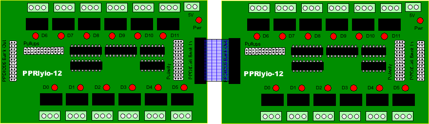
INote that there is nothing stopping you from creating an IDC ribbon cable with three headers on it to connect a single PPDIO96 bank to two PPRlyio-12 boards in parallel. Each PPRlyio-12 board represents three TTL loads so you could, conceivably, connect three (or possibly even four) PPRlyio-12 boards in parallel to a single PPDIO96 port.
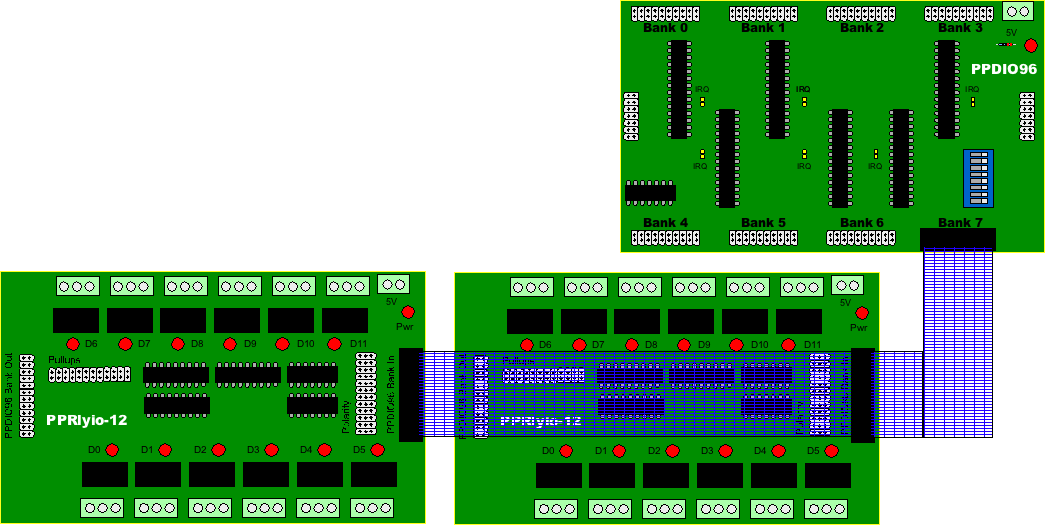
Daisy-chaining also works well for input as well as output. That is if you daisy-chain two PPRlyio-12 boards and then connect the PPDIO96 output connector to the PPDIO96 bank connector, then actuating one of the inputs (from an external source) will actuate two relays and make a single input available to the PPDIO96 input pin. Of course, it may be easier to simply wire the incoming signal to two separate inputs on the PPRlyio-12 input connector (though this does use up a pair of input pins on the PPDIO96, which might be an issue if you are running short on pins). The big advantage to using two inputs is that you only have to double up the exact number of inputs you need rather than having to use a whole extra PPRlyio-12 board.
Stand-alone Operation
Although the PPRlyio-12 design is part of the DAQ system it is quite possible to use the PPRlyio-12 board as a stand-alone relay board. All you need do is provide TTL-compatible signals to the inputs and the relays will respond accordingly. No software is necessary. If you want optical-isolated or dry contact inputs, just connect a PPOpto-12 board to the input connector (the PPOpto-12 will also operate in stand-alone mode without any other DAQ components).
Expanding Current-handling Capability
The relays and traces on the PPRlyio-12 board will handle 2.5A without too much difficulty (e.g., heating up the traces on the PCB). If you need to handle more current you can wire a pair of relays in parallel (and connect their input controls together, as well, or daisy-chain two PPRlyio-12 boards and wire the NC/NO and NO/NC contacts together). Just keep in mind that the relays will not close at exactly the same time (the relays are rated to close within about 10 mSec; so figure ±5 mSec worst case and you could see one relay closed with the other open for up to 10 mSec). As such, you shouldn't count on about more than a 50% increase in ampacity when wiring two relays in parallel. Note that the traces on the PCB could handle 5A for a brief period, they'll just warm up a bit; the longer you continue to feed 5A through the traces, the hotter the PCB will get (which is not a good thing). The PPRlyio-12 board has 100 mil traces on the top and bottom of the board, so heat dissapation shouldn't be a problem. In theory, it might have helped to put traces on the interior layers as well, but those layers don't disspate heat as well so the traces were only put on the top and bottom layers. In general, if you really want to control more than 2-3 amps, you should consider controlling an external (large) power relay with the relays on the PPRlyio-12 board.
Programming the PPRlyio-12 Board
You don't really program the PPRlyio-12 board directly. The PPRlyio-12 board generally connects to a PPDIO96 board and you program the MCP23S17 ICs on that board to read or write the inputs/outputs on the PPRlyio-12 board. However, there are a couple of things to keep in mind when programming the PPRlyio-12 board (via the PPDIO96). The most important thing to note is that relays are slow! If you're reading an input from the PPRlyio-12 and you see an input change, you cannot assume that the relay is in the appropriate position. It can take 10-20 milliseconds for the relay to open or close. If this can affect the operation of your software, you must take this fact into account.
Ditto for writing data to the PPRlyio-12 from the PPDIO96 board. When you write an output bit to the PPRlyio-12 that bit will pass through the board to the (digital) output pins almost instantaneously (well, subject to propagation delays). However, if the relay needs to change state that could take a while. When designing your system you must deal with the fact that it will take some time (typically 10-20 milliseconds) for the relays to actuate/deactuate when you write a new value to that output.