
Note: All photographs appearing on this page are freely usable for any purpose. Links to high-resolution versions of the pictures appear below each picture.
Digital Data Acquisition & Control System
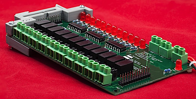
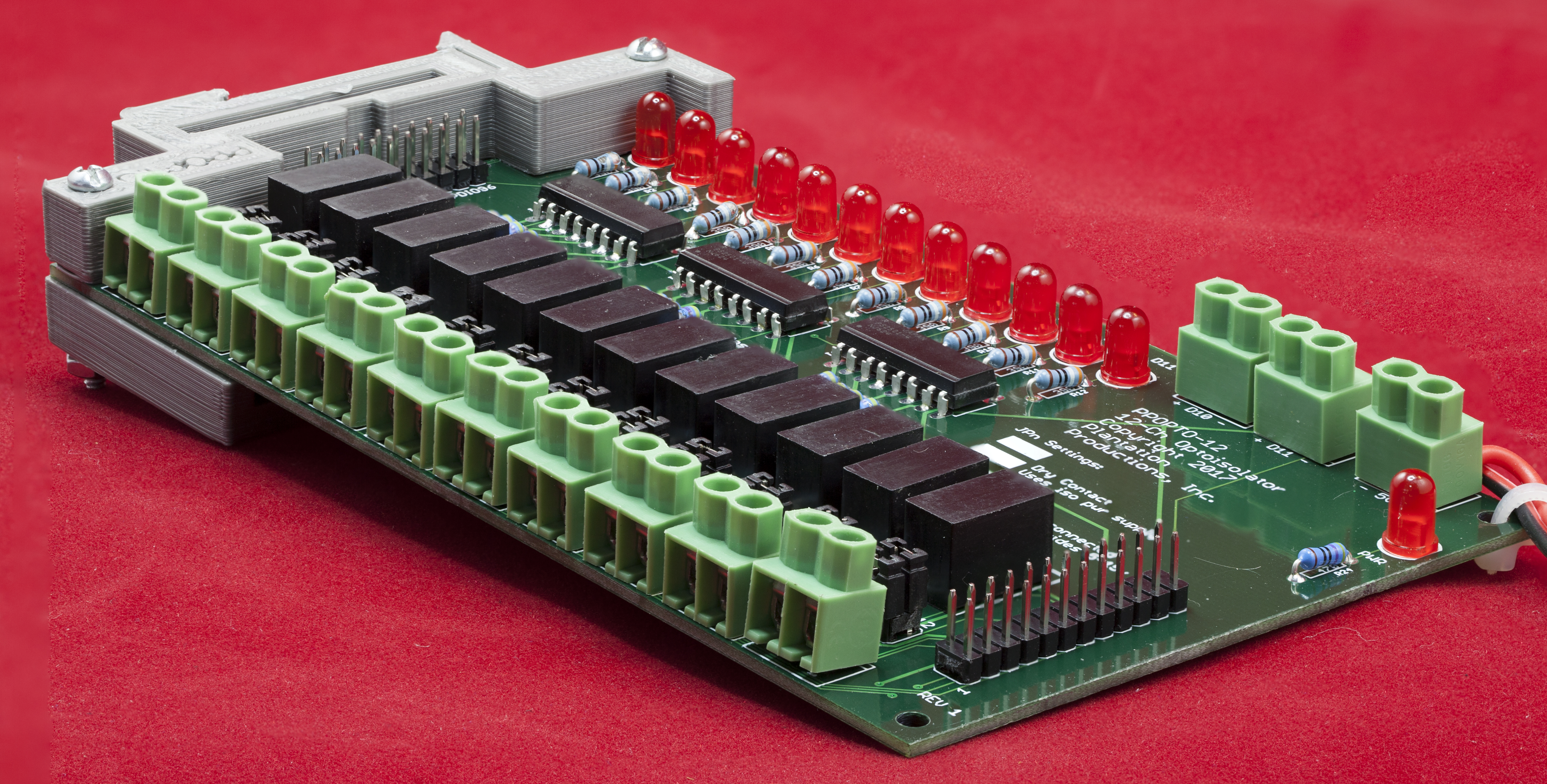
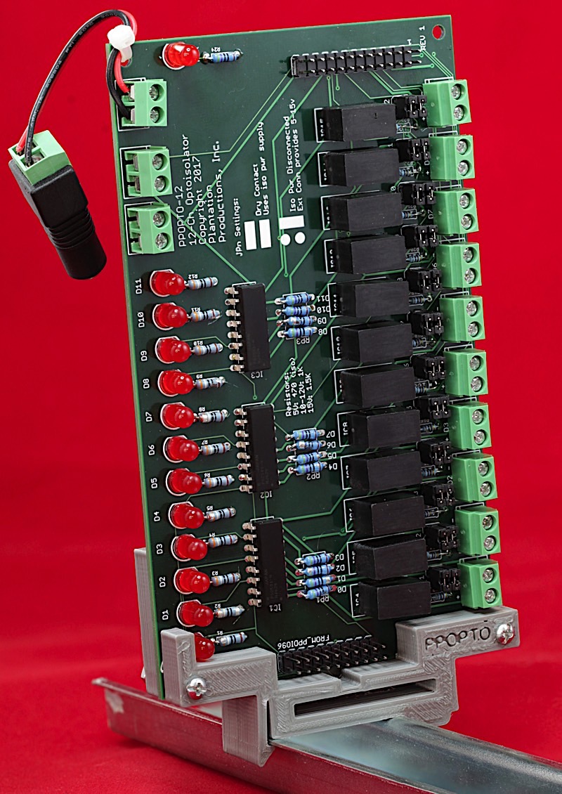
PPOpto-12
12-Channel digital input optical isolation
High-resolution image shot with a Canon EOS 5D MII
The PPOpto-12 board is a 12-channel opto-isolation board for digital input signals. It normally connects to one of the 12-channel banks on a PPDIO96 board (the PPDIO96 digital I/O board has eight 12-channel banks). The PPOpto-12 provides the following features:
- Open Hardware design based on Creative Commons 4.0 license
- Single 5V power supply input connector (screw terminals)
- LED indicates when power is applied
- 12 independent optically-isolated input channels
- PS2502-4 opto-isolator ICs provide 5kV to 7kV isolation (though the traces on the board are probably less than this; figure at least 1.5 kV isolation)
- An LED for each channel indicates whether the channel is active
- PPDIO96-bank-compatible ribbon cable connector (20-pin)
- 12 screw terminal input connectors
- 24-pin ribbon cable input connector (two pins for each channel, wired in parallel with the screw terminals)
- Each channel is jumper selectable for dry contact or logic-level input
- By swapping resistors, each channel can be programmed for 3.3V, 5V input, 10/12V input, 15V input, or even 24V input (in theory, you could select any input voltage you want although safety concerns limit the input voltage to around 30VDC)
- Each channel has its own isolation power supply (5V to 5V) so every channel is isolated from all the other channels and from the DAQ system circuitry
- DIN rail mounts allow the board to be optionally mounted in a vertical or horizontal orientation on a 35mm DIN rail
- Schematic and board layout are available in Eagle format
- DIN rail brackets are available in .STL format for 3D-printing
- Full documentation including System Requirements Specifications (SyRS), Hardware Requirements Specifications (HRS), Hardware Inspection list (HI), Hardware Test Cases (HTC), Hardware Test Procedures (HTP), Hardware Design Description (HDD), and (reverse) Traceability Matrix (RTM) are available for the DAQ system, including this board.
Bill of Materials (BOM) for the PPOpto-12 board:
- (13) 5mm LEDs
- (12) 390 Ω 1/4-watt 1% resistors
- (12) 100 Ω 1/2-watt 1% resistors (can substitute 220 Ω or 390 Ω for lower power consumption)
- (12) 470 Ω 1/4-watt 1% resistors (will use other values if digital inputs are logic levels other than 5V)
- (1) 220 Ω 1/4-watt 1% resistor
- (1) 20-pin (2x10) male header (ribbon cable connector)
- (1) 24-pin (2x12) male header (ribbon cable connector)
- (12) 4-pin (2x2) male headers
- 24 2-pin jumpers
- (3) PS2502-4 opto-isolator ICs
- (12) CRL2S 0505SC isolation power supplies (DC 5V-to-5V)
- (13) Two-terminal screw terminals (5mm/0.2" centers)
- (1) PPOpto-12 PCB
- Optional: one set of horizontal 35mm DIN rail mounts for DAQ boards
- Optional: one PPOPTO vertical 35mm DIN rail mount
Note: If you only want a few PPOpto-12 PCBs, contact Plantation Productions (randy@plantation-productions.com) to see if there are any in stock. Bare boards are $25 each plus shipping; fully assembled and tested boards are $399 each. If you need more than a couple PCBs and you're not in a huge hurry, it costs about $150 (plus about 4-6 weeks) to have a set of 10 manufactured and shipped to you from China. I use Seeed Studio Fusion PCD service (https://www.seeedstudio.com/fusion.html). The PPOpto-12 PCBs are four-layer boards. Here are the Gerber files for them (provide these files to Seeed Studio or your personal PCB manufacturer).
PPOPTO-12 Gerber Files for PCB
If you want to modify or enhance the PPOpto-12 design, or re-layout the PCB using Eagle, here are the Eagle files:
PPOPTO-12 Eagle files (Schematic and board layout)
If you simply want to view the schematic on-line, you'll find that here:
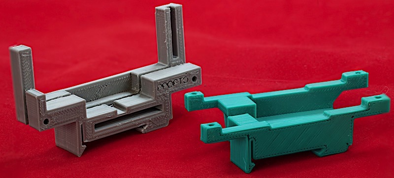
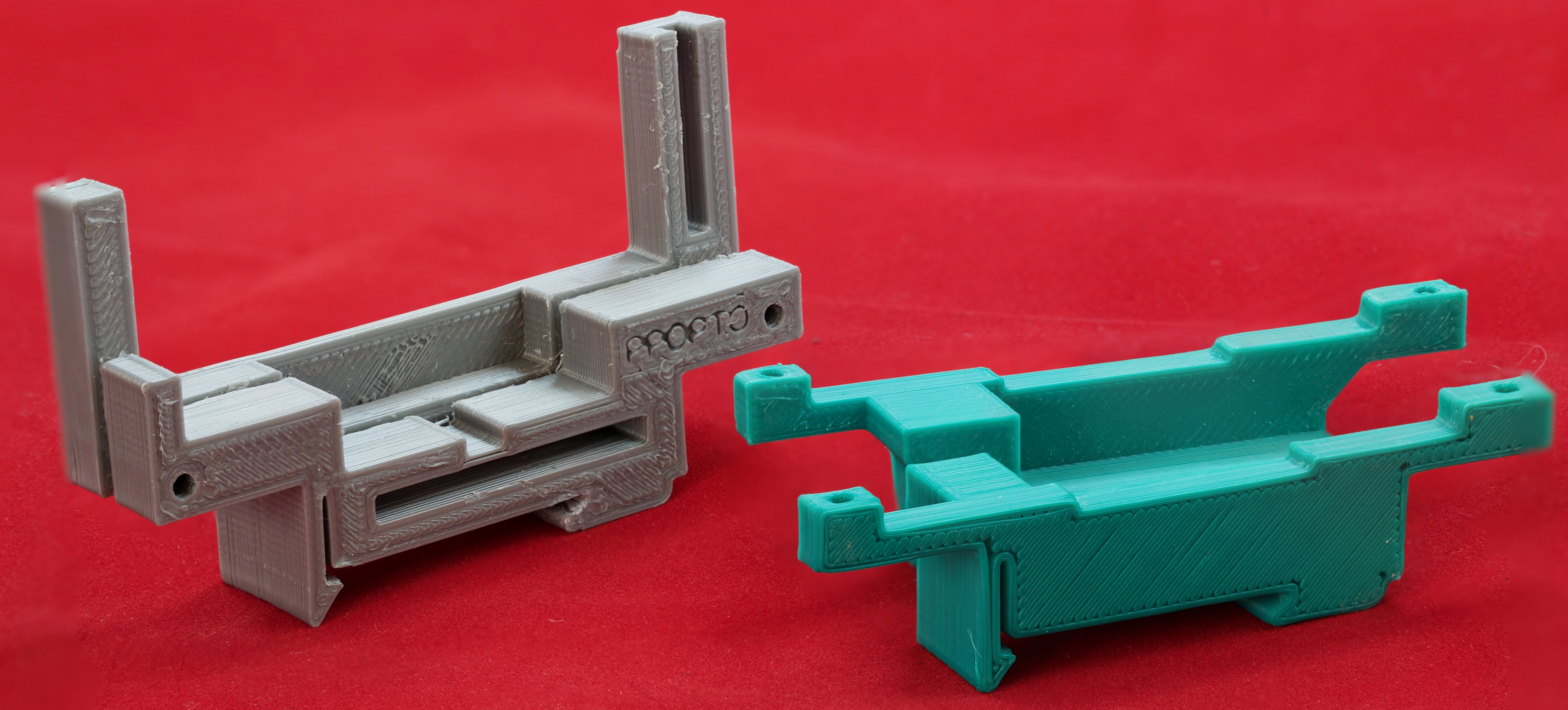
The DIN rails were created using AutoDesk's Fusion 360 (to produce STL files) and I personally print the results on a Lulzbot Taz6 3D printer using ABS filament (ABS is recommended for this job, PLA and PETG are a bit brittle). The STL files can be found here:
PPOPTO-12 DIN Rail Brackets 3D printer files
High-resolution image shot with a Canon EOS 5D MII
Here is a picture of the vertical DIN rail bracket and PPOpto-12 attached to a 35mm DIN rail. No picture for the horizontal DIN rail here, but the horizontal DIN rail is standard across all DAQ system boards. See the example on the PPDIO96 page if you want to see what the horizontal DIN rails look like.
High-resolution image shot with a Canon EOS 5D MII
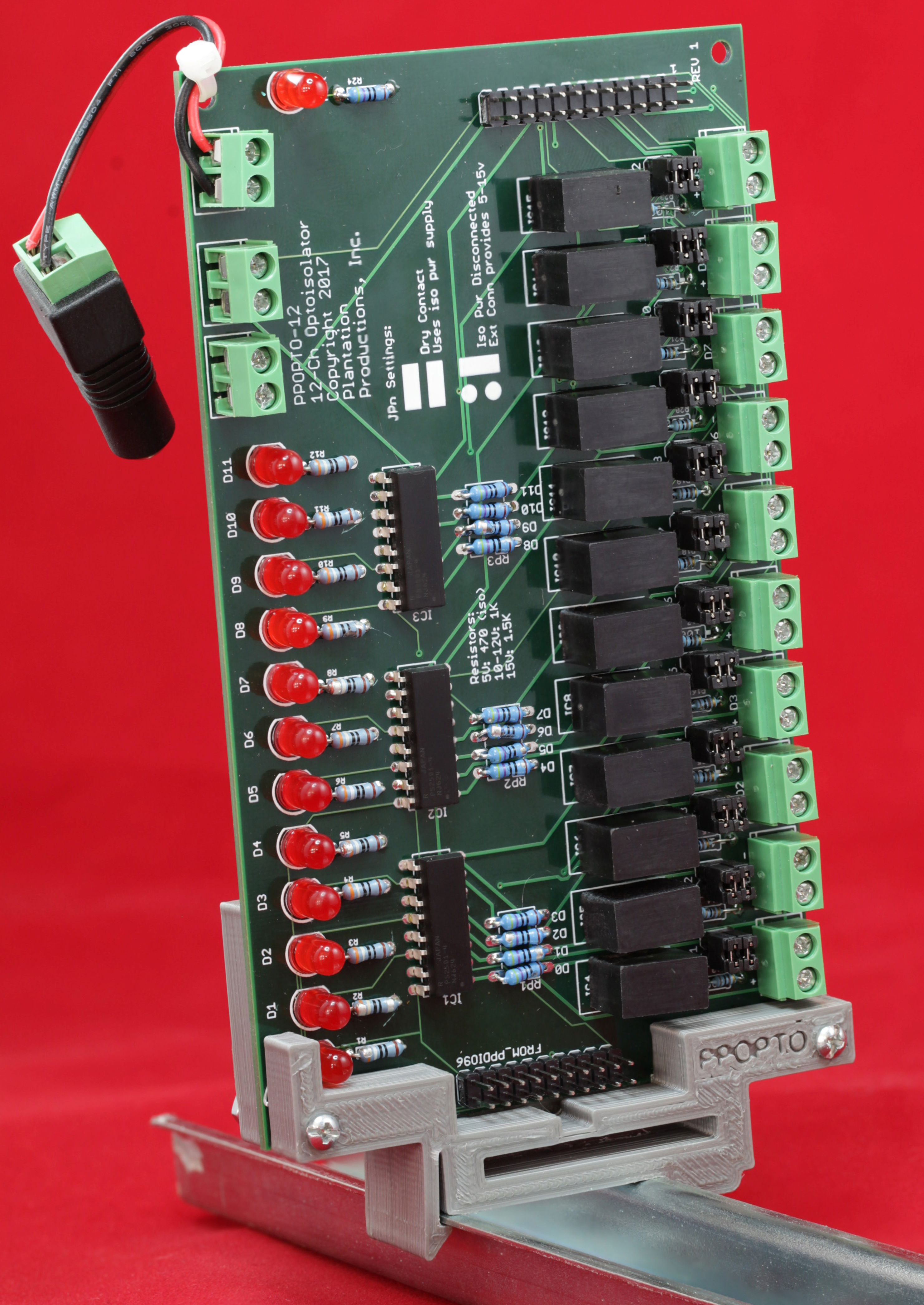
If you prefer, Plantation Productions, Inc., can provide a fully assembled and tested PPOpto-12 board with DIN rail brackets (horizontal and vertical) for $399. Contact randy@plantation-productions.com for more details.
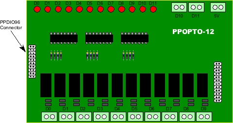
PPOpto-12 Board Layout
Connecting a PPOpto-12 board to a DAQ system or an EtherPort DIN Board
In theory, you could use a PPOpto-12 board independent of the DAQ system. The PPDIO96 connector contains 12 signal lines and 8 ground lines. The signal lines are TTL-logic compatible (5V) and reflect the state of the corresponding isolated input on the PPOpto-12 board. In practice, the PPDIO connector attaches to one of the eight banks on a PPDIO96 board, or to one of the four banks on a PPDIO-48 or EtherPort DIN board.
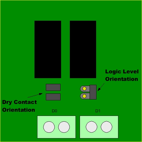
When connecting inputs to the PPOpto-12 screw terminals, there are a couple of issues to consider. First of all, you must have the two jumper pins associated with each channel set according to the type of input. For dry contact inputs (switches, relay contacts, and other "wire" connections that don't supply a voltage level) the jumper pins must have two jumpers installed in the horizontal orientation. For logic level inputs you must have one jumper installed in the vertical orientation on the right side of the jumper block.
Note that in "dry contact" mode, the PPOpto-12 board routes 5V from the CRL2S 0505SC isolated power supply onto the screw terminals (and input headers). Closing the switch contact connects the (isolated) 5V output from the CRL2S to the LED inside the PS2502-4 and activates that circuit. Opening the switch disconnects 5V and turns the internal LED off (thus registering a '0' on the output of that circuit). This implies that the circuitry attached to the opto-isolator input (screw terminals or 24-pin header) must be able to tolerate 5V and not affect that voltage (which is largely the definition of a "dry contact" input). Note that R13-R23 (100 Ω 1/2W resistors) exist to guarantee that the CRLS isolation power supplies are consuming at least 10% of their rated current/power. These power supplies are not regulated and will generate a much higher voltage (up to 15V) if they are supplying at least 10% of their rated power (2W). You can substitute a 220 Ω or 390 Ω 1/4 watt resistor in place of the 100 Ω 1/2W resistor. This will raise the output voltage of the CRLS 5V-5V isolation power supply by about 0.75V. For dry contact inputs, this won't matter at all and the board will wind up consuming significantly less power.
In "logic level" mode, the PPOpto-12 bypasses the isolation power supply completely and feeds the voltage level to the LED inside the PS2502-4 IC. For a TTL/5V logic level input, the PS2502-4 sees exactly the same voltage levels as in dry contact mode (as the CRL2S isolation power supply provides 5V).
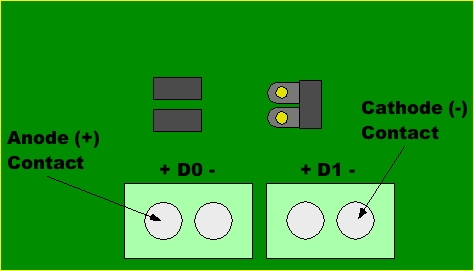
Because the PPOpto-12 inputs (in logic mode) drive an LED, polarity is very important. The terminal on the left side of each screw terminal is the anode (+) terminal. The terminal on the right side of each screw terminal is the cathode (-/Gnd) terminal.
Note: if a particular input channel on the PPOpto-12 board will always be used in logic level mode, you can save yourself a little money by not populating the CRL2S 0505SC module for that channel. The CRL2S modules run $10-$20 (US) and represent the most signficant cost in the BOM.
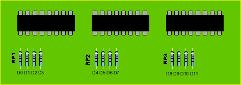
When operating the PPOpto-12 in logic level mode, be sure to install appropriate resistors in the RP1, RP2, and RP3 blocks on the board. These resistors vary depending on the input voltage. If the resistor values are too small, you risk damaging the internal PS2502-4 LEDs; if the resistors are too large, an "on" logic level may not activate the internal LED/photo transistor pair. The following are common resistor values:
| Input Voltage | Resistance |
| 5V | 470Ω |
| 10-12V | 1kΩ/1.2kΩ |
| 15V | 1.5K |
| 24V | 2.5K |
For system (and human) safety reasons, you should not normally apply more than about 30VDC to the inputs on the PPOpto-12 board.
In addition to the 12 screw terminal inputs, the PPOpto-12 also includes a 24-pin header with 12 pairs of pins wired in parallel with the screw terminal inputs.
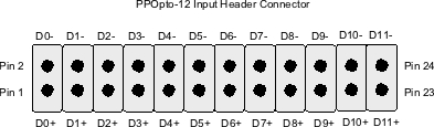
Note that the cathode pins would normally be connected to the signal's ground while the anode pins (+) are connected to the signal itself (when using logic level inputs). For dry contact inputs, the connection is arbitrary (dry contacts aren't polarized).