
Note: All photographs appearing on this page are freely usable for any purpose. Links to high-resolution versions of the pictures appear below each picture.
Digital Data Acquisition & Control System
PPBreakout
12-channel screw terminal breakout board
High-resolution image shot with a Canon EOS 5D MII
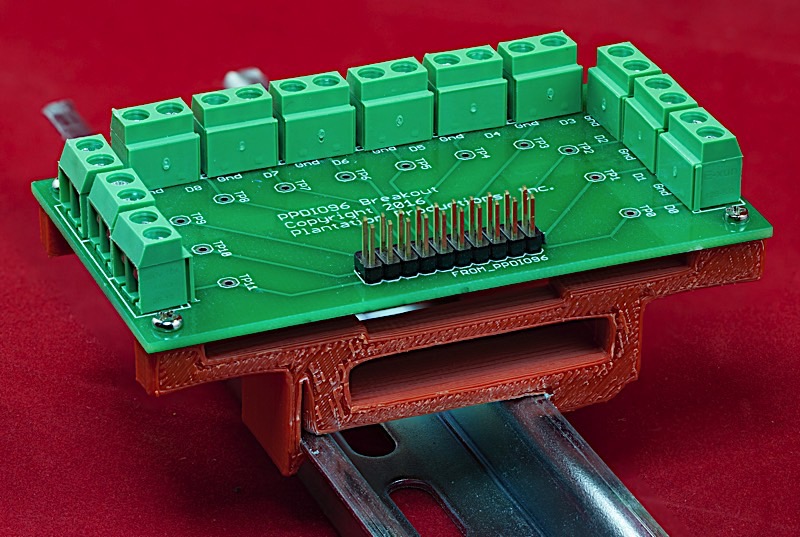
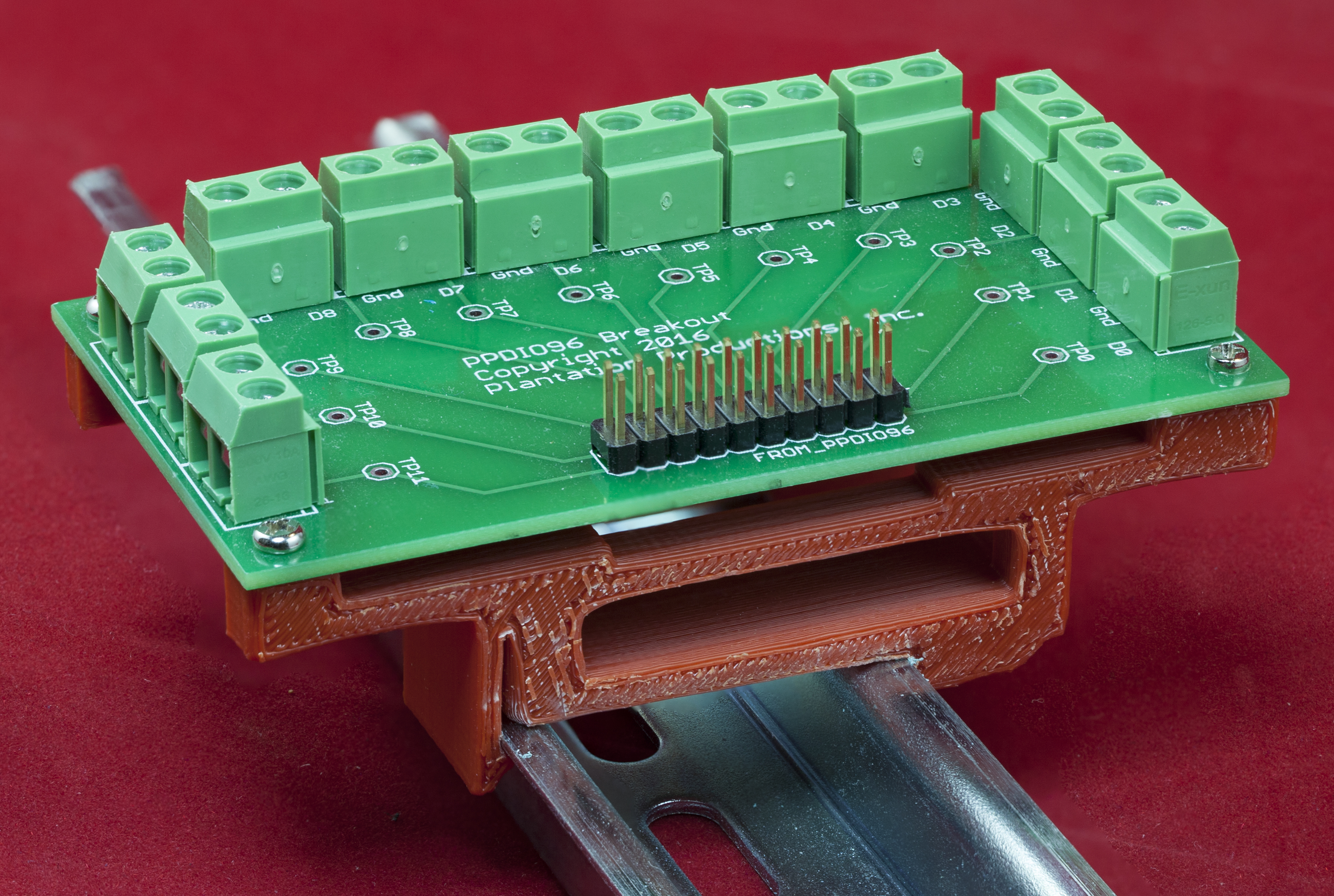
The PPBreakout board is a small adapter board that accepts a cable from a PPDIO96 bank connector and brings all the signals out to two-pin screw terminals. This breakout board is great when you have a set of TTL-logic-level signals you want to bring in to the PPDIO96 and you don't require the isolation or level-shifting capabilities of the PPOpto-12 board. The PPBreakout board is a simple, low-cost, two-layer circuit board with the following feature set:
- Low cost design
- Two-layer circuit board includes a ground plane on the bottom layer for noise reduction.
- Test pins for all active signals
- PPDIO96-bank-compatible 20-pin male header
- Two-pin screw terminals (signal+ground) for each of the 12 digital I/O signals present on each PPDIO96 bank that provide a signal/ground pair for each PPDIO96 digital signal pin
- Uses standard DAQ system 35mm DIN rail brackets
Bill of Materials (BOM) for the PPBreakout board:
- (1) 20-pin (2x10) male header (ribbon cable connector)
- (12) Two-terminal screw terminals (5mm/0.2" centers)
- (1) PPBreakout PCB
- Optional: one set of horizontal 35mm DIN rail mounts for DAQ boards
- Optional: (12) test pins
Note: If you only want a few PPBreakout PCBs, contact Plantation Productions (randy@plantation-productions.com) to see if there are any in stock. Bare boards are $5 each plus shipping. Fully assembled boards with DIN rail brackets are $35 each, plus shipping. If you need more than a couple and you're not in a huge hurry, it costs about $10 (plus about 4-6 weeks) to have a set of 10 manufactured and shipped to you from China. I use Seeed Studio Fusion PCD service (https://www.seeedstudio.com/fusion.html). The PPBrealout PCBs are two-layer boards. Here are the Gerber files for them (provide these files to Seeed Studio or your personal PCB manufacturer).
PPBreakout Gerber Files for PCB
If you want to modify or enhance the PPBreakout design, or re-layout the PCB using Eagle, here are the Eagle files:
PPBreakout Eagle files (Schematic and board layout)
If you simply want to view the schematic on-line, you'll find that here:
The DIN rails were created using AutoDesk's Fusion 360 (to produce STL files) and I personally print the rails on a Lulzbot Taz6 3D printer using ABS filament (ABS is recommended for this job, PLA and PETG are a bit brittle). The STL files can be found here:
PPBreakout DIN Rail Brackets 3D printer files
If you can live with just a pin-to-pin adapter (from each pin on the male PPDIO96 header to separate screw terminal pins) there is even a less expensive breakout board available from CHZ-Labs/Electronics Salon. Here are a couple variants:
Dual IDC-10 with DIN Rail mounts (around $20)
Dual IDC-10 w/o DIN Rail Mounts (around $11)
The difference between the PPBreakout and these boards is that there is a separate two-pin screw terminal block for each digital signal coming from (or going to) the PPDIO96 on the PPBreakout board (a total of 24 screw terminals). The Electronics Salon boards only have 20 screw terminals, so you will have to double up some ground wires on the eight available ground screw terminals.